Sonicaps and Resistors
Hi DennyG,
I suppose you are buying now so as to obtain the 20% discount - a good idea,
however I was going to recommend some more resistors also, and as Sonic Craft have suitable,
perhaps there is still time to add them to your Order if you email quickly to Sonic Craft, as I have read elsewhere that they are helpful to customers.
I presume you are keeping the original Celestion HF2000 tweeters.
If not, you will have to change the capacitor values for new tweeters.
To check that "little overbrightness",
listen to one of the revealing recordings, then disconnect one end of both the 82 ohm resistors and listen again.
Then reconnect the resistors and listen again.
If brighter with resistor disconnected then you can modify further there.
First, check the accuracy of the low ohms range of your multimeter.
The 2.7 ohm Mills are +/- 1% tolerance, therefore both will be within 2.67 <---> 2.73 ohms.
If your meter did not show within that range, then you will have to add or subtract the meter reading to/from the below:-
Measure the DC resistance of both your mid domes
-{and add or subtract any meter error if necessary, using 2.7 ohms as the Reference}.
If an MD measures less than 6 ohms, then buy 82 ohm in Mills MRA-12 for use with it.
If MD measures between 6 and 6.4 ohms, then buy 75 ohm to use with it.
If measures 6.5 ohm or a little greater, then buy 68 ohm.
Both MDs do not have to have the same value resistor, and if they differ by 0.3 ohm then using a different value resistor with each, as above, will cause them to match a little closer in sound in the upper midrange.
Buy also two of MRA-5 in 11 ohms, {or 10 ohms if 11 is sold out}.
I will be back - I have to change computers.
Hi DennyG,
I suppose you are buying now so as to obtain the 20% discount - a good idea,
however I was going to recommend some more resistors also, and as Sonic Craft have suitable,
perhaps there is still time to add them to your Order if you email quickly to Sonic Craft, as I have read elsewhere that they are helpful to customers.
I've installed the 2.7 ohm and 82 ohm resistors
With the limited listen I've had there is perhaps a little overbrightness (for want of a better term) in some material in the upper mid/treble??. However, as I've yet to fully evaluate them fully I can't be sure - will do so over the next month or so. 66's are very revealing.
I'm now keen to fine tune them. I guess the next thing would be to replace the mid and tweeter caps. Would the Sonicap Gen I be suitable or the ClarityCap PX. The Sonicaps have suitable values: 24uF, 6uF (and 6.2uF), 4uF all with a 200VDC rating (4x caps are about $70 from Sonicraft with 20% off this month = $56). ClarityCap PX have 25uF, 6uF and 3.9uF (4x caps are about $40 from Madisound). I can see you can pay a small fortune for caps! I want a good step up from the Solens but don't want to go overboard.
DG
I presume you are keeping the original Celestion HF2000 tweeters.
If not, you will have to change the capacitor values for new tweeters.
To check that "little overbrightness",
listen to one of the revealing recordings, then disconnect one end of both the 82 ohm resistors and listen again.
Then reconnect the resistors and listen again.
If brighter with resistor disconnected then you can modify further there.
First, check the accuracy of the low ohms range of your multimeter.
The 2.7 ohm Mills are +/- 1% tolerance, therefore both will be within 2.67 <---> 2.73 ohms.
If your meter did not show within that range, then you will have to add or subtract the meter reading to/from the below:-
Measure the DC resistance of both your mid domes
-{and add or subtract any meter error if necessary, using 2.7 ohms as the Reference}.
If an MD measures less than 6 ohms, then buy 82 ohm in Mills MRA-12 for use with it.
If MD measures between 6 and 6.4 ohms, then buy 75 ohm to use with it.
If measures 6.5 ohm or a little greater, then buy 68 ohm.
Both MDs do not have to have the same value resistor, and if they differ by 0.3 ohm then using a different value resistor with each, as above, will cause them to match a little closer in sound in the upper midrange.
Buy also two of MRA-5 in 11 ohms, {or 10 ohms if 11 is sold out}.
I will be back - I have to change computers.
continued ...
Sorry the above is a bit messy with not good phrasing in some places nor coherent explanations in others - I did not have time to Edit.
If you need sufficient time to listen to decide about the effects of the 82 ohm resistors, perhaps Sonic Craft will put your Order on Hold for a few days.
To date no-one's mid domes have measured larger DCRs, but if yours do, then Post here, as they may be OK to use 56 ohms resistors with.
Why this can work is that with slightly lower Impedance at the effective Load, the .34mH inductor will drop a little more of the upper-mids' signal.
There is a limit to how low in resistance the effective load can be made before an audible annomoly occurs elsewhere.
There is another way the upper mids can be reduced slightly, which I will explain when your new caps arrive.
The 200 volt rated versions of the Sonicaps will be fine I think.
{I will be trying some next year when I have time to get back to diy !}
I hope you bought the 4uF instead of the 3.9uF.
Whether you bought 6uF or 6.2uF may not matter much, but the 6uF may be slightly better in the treble.
The 24uF is closest to the optimum for the mids in the Sonicaps' range.
The 11 ohm in MRA-5 are to use with the Solen 6.2uF for those to be connected in Parallel with the lower measured 67uF caps that you have now in the T position of the bass filter.
Put the larger measured 6.2uF Solen with the 66uF, and the smaller 6.2 with the 67 Solen.
I'll explain more about that when the resistors arrive.
Measure all the caps when they arrive.
Put the two largest measured 4uF caps in the mids' filter, and the two smaller in the treble filter.
For all the caps, particually if significant measured differences, put the larger measured values in the filters for the smaller measured DCR drivers,
and the smaller meas'd caps with the larger meas'd DCR drivers,
as that will cause all to sound closer to pairs.
If you think I've forgotten something, then Post here.
Last edited:
Wayne Swann - interim
Hi Wayne,
of the 3 Files you included in Post #679 , the 1st and 2nd you had posted previously.
The 3rd one:
"measurements using new crossover.doc"
you had not previously posted.
This one shows part of what is wrong with that crossover, and as I had expected would show, and this is part of what you are hearing.
Basically, whilst attempting to alleviate a small audible anomoly, "John" has created a larger audible anomoly !
{perhaps inadvertantly}.
Before I type many words to explain that, open the File and look at the top lines above each graph.
First line is "Graphs".
Second line is "Print, Copy, Export, ..."
Third line is "SPL mag / SPL phase / Impedance / ... " , and in this third line you will see "Time domain".
Note that "SPL mag" is the selected option displayed as the graphs.
The same test signal that the computer received to obtain the "SPL mag" from has also given the computer the information for "Time domain",
and the information is already processed.
Now all that has to be done is the required button be pushed for the "Time domain" graphs to be displayed, from which they can be printed,
and likely the Files can be emailed to you.
Ask "John" to send you both those "Time domain" graphs, and Post them here.
You have paid for the Testing, thus you are entitled to see the results.
What you are hearing correlates to both what is in the "SPL mag" and in the "Time domain" graphs.
It will be simpler for me to explain both at the same time.
Celestion changed from 30uF to 24uF for good reason, and you should have done the same, {or to the very close 25uF option}.
Leave the "sound dampening" till you get the crossover right,
because any audible differences that may result from improvements in the dampening will be much smaller than the improvements that can be made to EVERY SECTION of that crossover !
Given the acoustic materials currently in the 66, and how they are placed, changes can cause the sound to be worse to greater degree than better,
and any possible better will not be to the degree of magnitude you heard as result of moving the crossover away from the large woofer magnet.
There are so many things you have asked me that I do not have time to address them all at the speed you seem to want to change at,
thus let's do things in manageable steps ... and you will be able to then assess the audible results of each step.
First let's see the "Time domain" results, and after that you can decide what you want to do next.
Also, it is difficult to determine where the sound is not as good.
I do have some issues regarding the midrange. I know that the designer, John, found there to be a dip in frequency reponse at 4,500 Hz on one of the midrange drivers. So he reduced the crossover point to 4000 Hz instead of the original 5000 Hz. I still need to speak to him regarding the possible impact this may be having on the midrange sound, as I believe this is now where the crossover to the tweeter takes place.
It's not always to determine which instruments/vocals etc. to listen out for between 4 - 5 KHz!
I know you have misgivings regarding the capacitor in the midrange circuit. This has now been changed to 27uF, which you believe to be too high. On my original crossovers this component was made up of a combination of 24uF & 6uF, creating a value of 30uF, which is higher still from what I have now.
I would really appreciate your additional views regarding the new midrange design and the change in crossover point from 5kHz to 4kHz, bearing in mind that one of the mid drivers had a large dip at 4.5kHz. I think I have already posted the various plots and graphs.
I would also very much appreciate your views regarding sound dampening of the speaker's cabinets.
Best Regards
Wayne
Hi Wayne,
of the 3 Files you included in Post #679 , the 1st and 2nd you had posted previously.
The 3rd one:
"measurements using new crossover.doc"
you had not previously posted.
This one shows part of what is wrong with that crossover, and as I had expected would show, and this is part of what you are hearing.
Basically, whilst attempting to alleviate a small audible anomoly, "John" has created a larger audible anomoly !
{perhaps inadvertantly}.
Before I type many words to explain that, open the File and look at the top lines above each graph.
First line is "Graphs".
Second line is "Print, Copy, Export, ..."
Third line is "SPL mag / SPL phase / Impedance / ... " , and in this third line you will see "Time domain".
Note that "SPL mag" is the selected option displayed as the graphs.
The same test signal that the computer received to obtain the "SPL mag" from has also given the computer the information for "Time domain",
and the information is already processed.
Now all that has to be done is the required button be pushed for the "Time domain" graphs to be displayed, from which they can be printed,
and likely the Files can be emailed to you.
Ask "John" to send you both those "Time domain" graphs, and Post them here.
You have paid for the Testing, thus you are entitled to see the results.
What you are hearing correlates to both what is in the "SPL mag" and in the "Time domain" graphs.
It will be simpler for me to explain both at the same time.
Celestion changed from 30uF to 24uF for good reason, and you should have done the same, {or to the very close 25uF option}.
Leave the "sound dampening" till you get the crossover right,
because any audible differences that may result from improvements in the dampening will be much smaller than the improvements that can be made to EVERY SECTION of that crossover !
Given the acoustic materials currently in the 66, and how they are placed, changes can cause the sound to be worse to greater degree than better,
and any possible better will not be to the degree of magnitude you heard as result of moving the crossover away from the large woofer magnet.
There are so many things you have asked me that I do not have time to address them all at the speed you seem to want to change at,
thus let's do things in manageable steps ... and you will be able to then assess the audible results of each step.
First let's see the "Time domain" results, and after that you can decide what you want to do next.
Last edited:
Hi DennyG,
I suppose you are buying now so as to obtain the 20% discount - a good idea, however I was going to recommend some more resistors also, and as Sonic Craft have suitable, perhaps there is still time to add them to your Order if you email quickly to Sonic Craft, as I have read elsewhere that they are helpful to customers.
I've emailed them re resistors. If they have already sent the parcel no matter I can get them later from them or parts connexion.
I presume you are keeping the original Celestion HF2000 tweeters. If not, you will have to change the capacitor values for new tweeters.
They still seem OK
To check that "little overbrightness", listen to one of the revealing recordings, then disconnect one end of both the 82 ohm resistors and listen again. Then reconnect the resistors and listen again.
If brighter with resistor disconnected then you can modify further there.
First, check the accuracy of the low ohms range of your multimeter. The 2.7 ohm Mills are +/- 1% tolerance, therefore both will be within 2.67 <---> 2.73 ohms. If your meter did not show within that range, then you will have to add or subtract the meter reading to/from the below:-
Measure the DC resistance of both your mid domes
-{and add or subtract any meter error if necessary, using 2.7 ohms as the Reference}.
If an MD measures less than 6 ohms, then buy 82 ohm in Mills MRA-12 for use with it.
If MD measures between 6 and 6.4 ohms, then buy 75 ohm to use with it.
If measures 6.5 ohm or a little greater, then buy 68 ohm.
Both MDs do not have to have the same value resistor, and if they differ by 0.3 ohm then using a different value resistor with each, as above, will cause them to match a little closer in sound in the upper midrange.
Buy also two of MRA-5 in 11 ohms, {or 10 ohms if 11 is sold out}.
I did measure one MD500 a while back and it was 7.2 ohm. Needs remeasuring as per your suggestion as I can't be sure of the accuracy. Also previously measured the two mids (MF500) I have in a non Celestion system and they were both 6.1 ohms.
Can't get back to this project till after Christmas Alan so I probably should order the 75, 68 (any maybe 56) MRA12's and the 11ohm MRA5 so I can experiment with them and the various mid drivers sometime in January. I have already the 82ohm MRA12 in circuit.
I will be back - I have to change computers.
To date no-one's mid domes have measured larger DCRs, but if yours do, then Post here, as they may be OK to use 56 ohms resistors with.
As mentioned in previous post one MD500 may be 7.2ohms.
Why this can work is that with slightly lower Impedance at the effective Load, the .34mH inductor will drop a little more of the upper-mids' signal.
There is a limit to how low in resistance the effective load can be made before an audible annomoly occurs elsewhere.
There is another way the upper mids can be reduced slightly, which I will explain when your new caps arrive.
The 200 volt rated versions of the Sonicaps will be fine I think.
{I will be trying some next year when I have time to get back to diy !}
I hope you bought the 4uF instead of the 3.9uF.
Yes
Whether you bought 6uF or 6.2uF may not matter much, but the 6uF may be slightly better in the treble.
I ordered the 6uF as I thought it may help the treble and I saw that Celestion reduced it in the later model
The 24uF is closest to the optimum for the mids in the Sonicaps' range.
24uF ordered
The 11 ohm in MRA-5 are to use with the Solen 6.2uF for those to be connected in Parallel with the lower measured 67uF caps that you have now in the T position of the bass filter.
Put the larger measured 6.2uF Solen with the 66uF, and the smaller 6.2 with the 67 Solen.
I'll explain more about that when the resistors arrive.
I'll probably do this part later to see the effect of the other changes first. Where do I put the 11ohm when it arrives and I do this bit?
Measure all the caps when they arrive.
Will do
Put the two largest measured 4uF caps in the mids' filter, and the two smaller in the treble filter.
Will do
For all the caps, particually if significant measured differences, put the larger measured values in the filters for the smaller measured DCR drivers,
and the smaller meas'd caps with the larger meas'd DCR drivers,
as that will cause all to sound closer to pairs.
OK
Hi DennyG,
I suppose you are buying now so as to obtain the 20% discount - a good idea,
however I was going to recommend some more resistors also, and as Sonic Craft have suitable,
perhaps there is still time to add them to your Order if you email quickly to Sonic Craft, as I have read elsewhere that they are helpful to customers.
Just received an email from USPS so the caps are on their way. I'll order the Mills MRA-12 in 75, 68, and 56ohm so all bases are covered & MRA-5 in 11ohm from partsconnexion next week
Mills resistors, continued ...
Hi Denny,
As you have already the 82 ohm in Mills you could try those with your MF versions of the mid-dome as they may be of close to same Impedance through-out their useable bandwidth.
DCR is only an estimate of what may be the case for Impedance through AC
- see all sba's measurements - and I note that his MFs are closer to equal than his MDs, though one of his MDs is more deteriorated than the other.
Really you would have to plot Impedance versus frequency to see the degree the samples may differ, thus what I have recommended for resistors is only an estimate, but it will get you closer than otherwise, and will work OK enough ... and if you do hear significant difference between each MD, {or each MF}, then you will have to investigate impedance versus frequency, etc ...
As you have the MF domes, those can be used in your 66s if one an MD fails.
What other drivers are in your "bespoke PTB" l'speakers ?
Before you buy any more resistors, do listen to the in/out with the 82 ohms to hear whether that is affecting part of what you are hearing in the upper mids,
though even if no obvious difference in upper mids the parallel connected resistors will relieve the old domes of a bit of stress around the lower crossover region, thus their life may be extended more than otherwise.
I see that both Parts Connexion and Sonic Craft have MRA-12 in 62 ohms,
and that would be a better option than 56 ohms, unless one MD is a lot higher DCR than the other.
My point about differing by more or less than 0.3 ohms is relevant to each type of dome only, thus don't worry if both MDs are higher than the MFs, but Post here if the MDs are very different to each other.
Do measure again with reference to the 1% accurate 2.7 ohm Mills pair {measure both of those},
because meters are often not very accurate in their low ohms range.
Zero the test leads before you measure, or if that is not possible, then touch them together and see the resistance of the wire that you will have to subtract from readings of low ohms' measurements.
11 ohms in MRA-5 is not available from Parts Connexion, but only from Sonic Craft, where they are cheaper, {though 10 ohms will suffice}.
Both companies' discounts are continuing till next week now !
Last edited:
Wayne Swann - consider this ...
Hi Wayne,
I have no doubt of that, being as "John" sells components,
however, with regard to the below - taken from one of the Files you posted:
"1. Near-field (measuring microphone at 5mm from dome grill) frequency response for both drivers. The manufacturer’s specified operating range is stated as 500Hz to 5kHz and this does appear to be the case (however, driver-A has a 5dB dip at about 4.5kHz compared to driver-B). With correct band-pass filter applied this driver could usefully be used in the range 500Hz to 4kHz, however fundamental resonance flattening (as shown above) is required.
Note: the SPL scale in this measurement is not an indicator of sensitivity due to the closeness of the microphone – driver sensitivity (2.83v/1m) will be measured when driver is mounted in a baffle. "
I'll continue this in the next Post, because my Edit period will expire before I get everything typed.
John has given me specifications for future upgrades when I have the money to do so.
Best Regards
Wayne
Hi Wayne,
I have no doubt of that, being as "John" sells components,
however, with regard to the below - taken from one of the Files you posted:
"1. Near-field (measuring microphone at 5mm from dome grill) frequency response for both drivers. The manufacturer’s specified operating range is stated as 500Hz to 5kHz and this does appear to be the case (however, driver-A has a 5dB dip at about 4.5kHz compared to driver-B). With correct band-pass filter applied this driver could usefully be used in the range 500Hz to 4kHz, however fundamental resonance flattening (as shown above) is required.
Note: the SPL scale in this measurement is not an indicator of sensitivity due to the closeness of the microphone – driver sensitivity (2.83v/1m) will be measured when driver is mounted in a baffle. "
I'll continue this in the next Post, because my Edit period will expire before I get everything typed.
Last edited:
continued from #688 above
As soon as "John" saw the differences between the two drivers he should have advised you one or both the following:
(1) - look in advertisments for at least 1, and preferably 2, more MD domes,
and have them measured in identical conditions to the two you own.
Hopefully another will be closer to a match with one of your domes,
{and there is reasonable likelihood of getting close to one of these},
and then the crossover will be simpler to achieve, and with less audible compromise than will be the case after trying to get these two to match.
Given the TWO distinct differences between the two MD samples
- the 4.5kHz region, and the 5.5kHz <--> 11kHz region -
it is not possible to match them via crossover at 4kHz.
Crossover would have to be about 2kHz to allow an Octave of same response from both drivers through the roll-off region.
{Wayne, you have seen only the frequency response for the smoother MD crossed to a tweeter. If you saw the plot for the notched MD, you would see that the notch is there in the combined response only a little reduced in level, and of the 5k5 <--> 11k region there will be a bit of a hump around 6kHz in the combined response.}
Crossing at 2kHz will result in a narrow bandwidth bandpass filter, and that sounds unpleasant - "shouty" would be how a reviewer may describe it.
3 octaves is about the minimum a bandpass filter can be before it becomes audibly unpleasant, and wider bandpass is audibly preferable if the drivers will allow for such. Note that the Celestion specification is one Decade bandpass, which is about 3.4 octaves.
(2) - a new mid-dome with very similar Frequency Response shape, and very similar Impedance versus Frequency shape, is the Morel EM 1308.
{ "John" sells these, thus he can measure samples and choose a closely matched pair in both Frequency and Impedance.}
This can be got to work with the existing Celestion specification crossover.
{EM 1308 specifications show slightly higher Impedance through the bandwidth, thus a suitable value of resistor can be connected in Parallel with the driver to reduce the entire Impedance to very close to the average of a Celestion MD500.}
The only consideration is whether EM 1308 can be got to fit neatly into the 66 baffle cutout.
{Likely it can - look at the published dimensions, then measure yours and compare.}
***
I do mean the Morel 1308 only, and not the MDM 55 because MDM 55 will require a different crossover circuit AND can not be got to work to as low a frequency as the Celestion domes, thus would have to be crossed higher and that will allow the resonance fault in the Celestion woofer cone between 700 and 800 Hz to be more audible.
Also, I do not recommend the Scan Speak Discovery mid-domes
{which John also sells}
because despite being "ScanSpeak" manufactured these are not the equivalent of the higher quality Scan drivers.
The Discovery series of drivers are average quality drivers built down to a price to compete with other manufacturers' mid-price drivers,
and neither version of their mid-dome can be got to work with smooth response of sufficient bandwidth to better the Celestion domes.
I strongly recommend you consider the above and decide one of those options, because your money will be better spent there than on expensive crossover components which can NEVER cause your existing MDs to match.
If you end up with four MD domes, you can easily sell the two you don't want, because there are plenty of buyers who are not fussy listeners
{like you and I are !}.
Another alternate is to buy 3 or 4 MF versions of the dome, and have those measured to find a pair.
It is possible to get something towards a better match than you currently have, and that is done by using a slightly different shaped filter for each MD, as follows:
"Driver A" {as its referred to in your File, and the other as "driver B"} requires a steep slope filter at a little above 5kHz
{the exact frequency I would have to find by experiment}.
A Chebychev 2nd order will suffice, as that will partially fill the 4.5kHz notch
{only partially fill, as it is not possible to fill it entirely without very audibly unpleasant compromise}
and will also reduce the 5.5kHz <--> 11kHz region sufficiently for a gentler sloped 2nd order filter used with "driver B" somewhere above 6kHz
{the exact frequency I would have to find by experiment}
to result the same roll-off slope for both drivers above 6kHz.
The different shaped filters will be counter-balanced by the different shaped driver responses, thus if the filters are carefully designed the sound from both drivers will be closer to same than will be otherwise the case.
***************
About the "near-field", "5mm" measuring distance used for the domes' comparison plots:
This is a valid technique, but has to be done very carefully because if there is even a small difference in microphone position for one dome than for the other such position difference will exaggerate any differences between the two domes.
Also, at 5mm distance there will be some reflections between microphone and dome, albeit affecting the measurements higher in frequency than that 4.5kHz anomoly.
Being 5mm, I recommend you ignore the plots responses at 10kHz and above, as reflections and tiny position differences could have caused those anomolies.
The anomolies in "driver A" between 4kHz and 6kHz {versus "driver B"} could have been caused by, or exaggerated by a slight angle difference of the microphone from that used for "driver B".
I would have to do these measurements myself to be confident of them,
however that is not stating that "John" is not competant there, but stating only where one has to be very careful.
Last edited:
DCR is only an estimate of what may be the case for Impedance through AC
- see all sba's measurements - and I note that his MFs are closer to equal than his MDs, though one of his MDs is more deteriorated than the other.
Really you would have to plot Impedance versus frequency to see the degree the samples may differ, thus what I have recommended for resistors is only an estimate, but it will get you closer than otherwise, and will work OK enough ... and if you do hear significant difference between each MD, {or each MF}, then you will have to investigate impedance versus frequency, etc ...
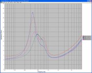
I did some impedance vs freq tests on drivers a while back using Speaker Workshop. I need to repeat one MD500 as it appears to be high by about 1/2 an ohm. This is the MD500 I reported previously as having a DCR of 7.2 ohms so maybe this is for real! A chart for the mids is attached.
All four mids seem to have similar shapes to those reported by sba in his chart called 'mid-dome impedance 7-2010.png' so I guess I am on the right track with these measurements.
As you have the MF domes, those can be used in your 66s if one an MD fails.
What other drivers are in your "bespoke PTB" l'speakers ?
The PTB drivers are:
Celestion MF500 mids (marked as 50W, Range 0-5-5kHz, 8ohm, 2" dome),
Vifa D25AG-35 tweeter (marked as 6ohm),
Onkyo W-30A MkII-F woofer (marked as 30W max 60W, 8ohm) it is 10" dia.
The woofer is in a sealed cabinet about 15" W x 20" H x 27" D. The other drivers are in a small separate triangular box.
Attachments
mids freq response chart
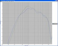
Alan, Looking at your comments on the WayneSwann mid driver freq charts I would welcome your comments on these nearfield freq plots I did a while back on the two PTB mids when I was learning to use the software. They were taken at the same equipment settings using Behringer mic & pre amp.
Alan, Looking at your comments on the WayneSwann mid driver freq charts I would welcome your comments on these nearfield freq plots I did a while back on the two PTB mids when I was learning to use the software. They were taken at the same equipment settings using Behringer mic & pre amp.
Attachments
Plots in #690 and #691
Hi DennyG,
briefly today as I have only a little time available.
Impedance plots:
you could do them again, or at least the two MD plots, to check there was no inadvertant errors made during measurement.
As you have the 82 ohm resistors installed in the mids' filters, you can install the MF domes for listening whilst you re-test the MDs.
If you install to the MF domes, do listen carefully to hear if those have similar or different upper midrange prominence to that you reported for the MDs after the new resistors were installed.
The Orange MD has some loss of damping of its Fs,
and if the Plot is correct, it has also a slightly higher resistance voice-coil than the others.
That will not be a problem if there is no damage to the voice-coil.
Do you hear any slight clicking or buzzing of that MD during loud passages of music ?
If no faults, the Impedance difference can be mostly compensated for by using a lower parallel resistor with that one than with the other MD.
I will return about this when I have time available,
but check now the above if you have time, and Post here.
The Pink MD seems in good condition, so far as its Impedance plot can indicate.
The Blue MF has some loss of damping, but seems otherwise OK so far as its Impedance plot can indicate.
The Green MF is some-what faulty.
See the higher in Fs frequency than the other domes {even though lower in magnitude}
- see sba's 2009 Impedance plots of the 6 samples where the Yellow sample has a similar Impedance plot to your Green,
and my comments about it some time after then.
Also for your Green, see the sag in its Impedance curve between about 3.5kHz and 9kHz.
That indicates a fault ... I'll think what it may be, and two things immediately come to mind.
If it is working, then try it at low volume level then slowly increase volume if no audible problems.
The near-field Frequency Response plots:
Is the Blue here the same MF as the Blue of the Impedance plot,
and the Green here the same as the Green of the Impedance plot ?
I think they are, but please do confirm this.
If they are the same in both as colour coded, then were both measured with EXACTLY the same level of Test Signal ?
... and were both measured from EXACTLY the same microphone distance and angle ?
If yes to both above, then see the higher output of the Green MF, especially around 900 Hz.
This would correlate with its fault in its low frequency damping.
See also the dip in its output between about 5.5kHz and 7.5kHz {versus the Blue sample}.
this would correlate with the Impedance droop which that portion of the bandwidth is contained with-in.
The Green may still be quite useable, but listen now to check and compare its sound to the Blue, and if any audible faults, then look for another MF to buy ... and perhaps another MD if the price seems reasonable.
Last edited:
Plots in #690 and #691
Hi Alan,
Thanks for your evaluation of the plots. I'll repeat the tests next month when I can get back to it. I also want to check out other test software. Do you know what software others use, sba in particular?
Haven't noticed any buzzing, clicking in the orange MD. But will do futher checks later. I decided to hold off ordering resistors from N America. Jaycar have 68R and 47R, 10W wirewound I can easily get. They also have a good range in 10W from 3R3 to 10R and above. Do you think 68R will be about right for the compensation to the orange MD
The green MF is working but if you can provide a reason for the faults in the plots then that would be helpful. I can see I need to listen carefully here as well.
Freq plots:
Yes the blue and green represent the same drivers in both the impedance and freq plots. I've named the four drivers as MD500L, MD500R, MF500L, MF500R to ensure consistency throughout.
I measured the MF's at the same time with the same settings. I think I was getting the hang of the software and finally started getting repeatable readings. My aim was to get comparative freq responses. The mic/preamp setup has not been calibrated.
DG
sba's measurements and Software
Hi Denny,
sba started posting about his measurements and software in #344 on Page 35.
He continues through Page 36, and on Page 37 in #366 he posted more about the type, and again in #377 on Page 38.
I recommend you read those, and my comments following those, plus look at the Links he posted to some Software programs in the above.
sba studies Software to greater degree than I do.
Hopefully he will see this, and your question above sometime and Post more about the programs if necessary.
His later set of measurements start on Page 49, and there is more about Software somewhere amongst those, or a bit later on.
I think you were wise to not buy more resistors now.
Better will be for me to think about the specific values after I see your next set of measurements.
Stay with the 82 ohm resistors in for now, and do some careful comparative listening of your MF versus MD domes,
and if any obvious differences audible between each MD and each MF.
When you install the Sonicaps, measure your 2.7 ohm resistors so that you can assess the Accuracy of the low ohms' scale of your meter.
The range that includes 2.7 ohms will also include the 6 <---> 7 ohms region where the DCRs of the drivers are.
I have to go now - more next time.
Last edited:
Hi Alan,
Sorry about the format of the previous extracts, but I have tried to encompass most of your misgivings about my new crossover design.
I have been doing a lot of listening to various types of music.
The problem I have is one that you pointed out a long time ago, and that is that so much has been changed it is difficult to pinpoint the exact nature of the improvements in the sound they now produce. Also, it is difficult to determine where the sound is not as good. The one thing that is clear is they have a different sound from the original speakers I had. This of course is bearing in mind that I originally inherited the Realistic Super-Tweeters having been used to replace the original HF2000's.
The bass is much tighter and it's easier to follow bass lines. The new SEAS Tweeters sound good, and I have been pleasantly surprised about the improved clarity of the vocals, especially female vocals. I do have some issues regarding the mid range. I know that the designer, John, found there to be a dip in frequency response at 4,500 Hz on one of the mid range drivers. So he reduced the crossover point to 4000 Hz instead of the original 5000 Hz. I still need to speak to him regarding the possible impact this may be having on the mid range sound, as I believe this is now where the crossover to the tweeter takes place.
It's not always to determine which instruments/vocals etc. to listen out for between 4 - 5 KHz!
I know you have misgivings regarding the capacitor in the mid range circuit. This has now been changed to 27uF, which you believe to be too high. On my original crossovers this component was made up of a combination of 24uF & 6uF, creating a value of 30uF, which is higher still from what I have now.
I am also rather wresting with the issue of how much internal sound dampening I should use. As I previously said, with the use of an ABR it kind of makes the speaker design somewhere between an infinite baffle and a ported design.
I would really appreciate your additional views regarding the new mid range design and the change in crossover point from 5kHz to 4kHz, bearing in mind that one of the mid drivers had a large dip at 4.5kHz. I think I have already posted the various plots and graphs.
As I have previously said, this is not my final attempt at designing the crossover circuitry. John has given me specifications for future upgrades when I have the money to do so. I do however realise that you cannot base your entire design using testing measurements alone, and that it is as you have said, a compromise!.
I would also very much appreciate your views regarding sound dampening of the speaker's cabinets.
Best Regards
Wayne
Hi Alan,
I really would appreciate your views regarding my new crossover specifications, now that you possibly have had a little more time to look at the design. I hope I have answered any questions you have. I know you do not feel it's the optimum design but as I said, for me it's still a 'work in progress', and I would like to know you opinion of where the best improvements could be made using this new design as a starting point.
I also would really appreciate you views regarding the internal sound dampening, and how it should be approached? Due to the ABR which kind of makes it somewhere between design philosophies.
Also, would anyone be interested in my old Celestion 66's crossovers. They are none the less working perfectly well in their original format.
Best Regards
Wayne
correcting an error in my #689, plus refs for Wayne Swann
Correction to my Post #689:
where I used the word "slope" I should have used the word "corner", because both filters will eventually move to the same slope.
Their initial corner is where they need to be different.
Below is reproduced the relevant section of my #689, and now includes the correction.
Hi Wayne,
I have replied to your earlier Post, the one you repeated in #695.
See on Page 69 my Posts: #683; #688; #689.
I will continue my evaluation of that crossover when I have the time available.
I will be able to do that more efficiently if you can post the Time Domain information I mentioned in one of my listed replies, and any other measurements you have not posted yet may be helpful also.
I recommend that you do not sell your old crossovers until you have at least considered what I wrote, because you may later decide to return to using the .34mH inductor in the mids and the .14mH inductor in the treble after you have realized what is realistically possible and what isn't.
Additionally, the midrange will sound better controlled with your original 2.2mH inductor installed, because some resistance is required in that circuit position to control the resonance of the filter.
That Parallel connected inductor's resistance does not attenuate the level of signal to the mid driver in the way that the resistance of the inductors connected in Series did for the bass driver, because it is connected in Parallel and not in Series.
Correction to my Post #689:
where I used the word "slope" I should have used the word "corner", because both filters will eventually move to the same slope.
Their initial corner is where they need to be different.
Below is reproduced the relevant section of my #689, and now includes the correction.
It is possible to get something towards a better match than you currently have, and that is done by using a slightly different shaped filter for each MD, as follows:
"Driver A" {as its referred to in your File, and the other as "driver B"} requires a steep corner filter at a little above 5kHz
{the exact frequency I would have to find by experiment}.
A Chebychev 2nd order will suffice, as that will partially fill the 4.5kHz notch
{only partially fill, as it is not possible to fill it entirely without very audibly unpleasant compromise}
and will also reduce the 5.5kHz <--> 11kHz region sufficiently for a gentler corner 2nd order filter used with "driver B" somewhere above 6kHz
{the exact frequency I would have to find by experiment}
to result the same roll-off slope for both drivers above 6kHz.
The different shaped filters will be counter-balanced by the different shaped driver responses, thus if the filters are carefully designed the sound from both drivers will be closer to same than will be otherwise the case.
.
Hi Wayne,
I have replied to your earlier Post, the one you repeated in #695.
See on Page 69 my Posts: #683; #688; #689.
I will continue my evaluation of that crossover when I have the time available.
I will be able to do that more efficiently if you can post the Time Domain information I mentioned in one of my listed replies, and any other measurements you have not posted yet may be helpful also.
I recommend that you do not sell your old crossovers until you have at least considered what I wrote, because you may later decide to return to using the .34mH inductor in the mids and the .14mH inductor in the treble after you have realized what is realistically possible and what isn't.
Additionally, the midrange will sound better controlled with your original 2.2mH inductor installed, because some resistance is required in that circuit position to control the resonance of the filter.
That Parallel connected inductor's resistance does not attenuate the level of signal to the mid driver in the way that the resistance of the inductors connected in Series did for the bass driver, because it is connected in Parallel and not in Series.
Last edited:
As soon as "John" saw the differences between the two drivers he should have advised you one or both the following:
(1) - look in advertisments for at least 1, and preferably 2, more MD domes,
and have them measured in identical conditions to the two you own.
Hopefully another will be closer to a match with one of your domes,
{and there is reasonable likelihood of getting close to one of these},
and then the crossover will be simpler to achieve, and with less audible compromise than will be the case after trying to get these two to match.
Given the TWO distinct differences between the two MD samples
- the 4.5kHz region, and the 5.5kHz <--> 11kHz region -
it is not possible to match them via crossover at 4kHz.
Crossover would have to be about 2kHz to allow an Octave of same response from both drivers through the roll-off region.
{Wayne, you have seen only the frequency response for the smoother MD crossed to a tweeter. If you saw the plot for the notched MD, you would see that the notch is there in the combined response only a little reduced in level, and of the 5k5 <--> 11k region there will be a bit of a hump around 6kHz in the combined response.}
Crossing at 2kHz will result in a narrow bandwidth bandpass filter, and that sounds unpleasant - "shouty" would be how a reviewer may describe it.
3 octaves is about the minimum a bandpass filter can be before it becomes audibly unpleasant, and wider bandpass is audibly preferable if the drivers will allow for such. Note that the Celestion specification is one Decade bandpass, which is about 3.4 octaves.
(2) - a new mid-dome with very similar Frequency Response shape, and very similar Impedance versus Frequency shape, is the Morel EM 1308.
{ "John" sells these, thus he can measure samples and choose a closely matched pair in both Frequency and Impedance.}
This can be got to work with the existing Celestion specification crossover.
{EM 1308 specifications show slightly higher Impedance through the bandwidth, thus a suitable value of resistor can be connected in Parallel with the driver to reduce the entire Impedance to very close to the average of a Celestion MD500.}
The only consideration is whether EM 1308 can be got to fit neatly into the 66 baffle cutout.
{Likely it can - look at the published dimensions, then measure yours and compare.}
***
I do mean the Morel 1308 only, and not the MDM 55 because MDM 55 will require a different crossover circuit AND can not be got to work to as low a frequency as the Celestion domes, thus would have to be crossed higher and that will allow the resonance fault in the Celestion woofer cone between 700 and 800 Hz to be more audible.
Also, I do not recommend the Scan Speak Discovery mid-domes
{which John also sells}
because despite being "ScanSpeak" manufactured these are not the equivalent of the higher quality Scan drivers.
The Discovery series of drivers are average quality drivers built down to a price to compete with other manufacturers' mid-price drivers,
and neither version of their mid-dome can be got to work with smooth response of sufficient bandwidth to better the Celestion domes.
I strongly recommend you consider the above and decide one of those options, because your money will be better spent there than on expensive crossover components which can NEVER cause your existing MDs to match.
If you end up with four MD domes, you can easily sell the two you don't want, because there are plenty of buyers who are not fussy listeners
{like you and I are !}.
Another alternate is to buy 3 or 4 MF versions of the dome, and have those measured to find a pair.
It is possible to get something towards a better match than you currently have, and that is done by using a slightly different shaped filter for each MD, as follows:
"Driver A" {as its referred to in your File, and the other as "driver B"} requires a steep slope filter at a little above 5kHz
{the exact frequency I would have to find by experiment}.
A Chebychev 2nd order will suffice, as that will partially fill the 4.5kHz notch
{only partially fill, as it is not possible to fill it entirely without very audibly unpleasant compromise}
and will also reduce the 5.5kHz <--> 11kHz region sufficiently for a gentler sloped 2nd order filter used with "driver B" somewhere above 6kHz
{the exact frequency I would have to find by experiment}
to result the same roll-off slope for both drivers above 6kHz.
The different shaped filters will be counter-balanced by the different shaped driver responses, thus if the filters are carefully designed the sound from both drivers will be closer to same than will be otherwise the case.
***************
About the "near-field", "5mm" measuring distance used for the domes' comparison plots:
This is a valid technique, but has to be done very carefully because if there is even a small difference in microphone position for one dome than for the other such position difference will exaggerate any differences between the two domes.
Also, at 5mm distance there will be some reflections between microphone and dome, albeit affecting the measurements higher in frequency than that 4.5kHz anomoly.
Being 5mm, I recommend you ignore the plots responses at 10kHz and above, as reflections and tiny position differences could have caused those anomolies.
The anomolies in "driver A" between 4kHz and 6kHz {versus "driver B"} could have been caused by, or exaggerated by a slight angle difference of the microphone from that used for "driver B".
I would have to do these measurements myself to be confident of them,
however that is not stating that "John" is not competant there, but stating only where one has to be very careful.
Hi Alan,
I understand what you are saying, I must admit that when John told me about the dip @4.5kHz on one of the MD500's I thought it a bit odd, but he seemed to portray it as not a problem, saying it could be compensated for in the crossover design.
The first question I asked him after receiving the MD500's, the new SEAS tweeters and the finished crossovers from him was 'which crossover should be used on the MD500 with the "Dip"'? When he said they were both the same I was somewhat surprised!
Anyway, after reading what you have said I would rather go down the route on purchasing new mid-range units. I don't want to chance picking up a previously used MD500 as in all probability it to could have some kind of defect. Plus, I do not have the necessary testing equipment for checking them out.
I sent John an email outlining the the mid range dip I was experiencing with the new crossovers. One thing I didn't mention (because I forgot!) was regarding the comment you made about the vocals being 'shouty', which I have definitely noticed!
I asked him to let me have a new graph using the 'Time Domain' option if he still had the necessary data to provide it.
The reply I got from him basically gave me some new values for one of the 'Caps' and one of the 'Inductors' within the mid ranges crossover network. I have attached his reply as well as the new crossover layout.
He also provided a new graph but it was using the same option as he had given me before, namely, 'SPL Mag'. So I'm not really sure if this helps. He didn't mention anything about the 'Time Domain' option.
I also said that I was looking at the Morel EM 1308 mid range drives as a possible replacement of the MD500's. He did in fact mention that he had previously used one of the Scanspeak mid range drivers as a replacement in one of his earlier Celestion 66 conversions with a great deal of success.
From what you say I would rather go with the Morels.
Also, I really do not want to use any parts from the old crossovers. It must be possible to replace any of those components with something newer and more technically advanced? I know how you feel regarding the various compromises and nuances of the original crossovers, but I am pretty dogmatic in this desire to use more up-to-date components. Especially as I've spent a lot of money so far and I want to get this right. I know that if I hadn't been so hasty I would have ended up spending considerably less, but this experience is good for me to carry forward into the future!
I have attached the various bits of information I received from John for your perusal. I do have to say that I believe John to be a very experienced technician, therefore I do respect his opinions. But I guess he is possibly looking at things from a different point of view, using the components and rationale he has been used in the past. He has gone through several major Celestion 66's modification projects. What I need to do is balance all of the views put forward and hopefully come up with a successful result. I must admit I thought things would have been more clear cut than this project has become, but it's all good stuff as far as I'm concerned.
Best Christmas Regards
Wayne
Attachments
I sent John an email outlining the the mid range dip I was experiencing with the new crossovers. One thing I didn't mention (because I forgot!) was regarding the comment you made about the vocals being 'shouty', which I have definitely noticed!
I asked him to let me have a new graph using the 'Time Domain' option if he still had the necessary data to provide it.
The reply I got from him basically gave me some new values for one of the 'Caps' and one of the 'Inductors' within the mid ranges crossover network. I have attached his reply as well as the new crossover layout.
Hi Alan,
just for your information, here is a copy of the email text I sent to John.
"Hi John,
I have been listening to my Celestions some more. I think there maybe an anomaly around the mid-range crossover to the new SEAS tweeters. I noticed it when I first started listening to some familiar old tunes but I thought it would settle down after the initial 'running in' period. I'm not sure but I think some of the character of the upper mid-range drives has been lost. You know well enough that I am not technically equipped to interpret the various graphs etc, but do you think that this could be due to the change caused by the 'drop' at 4.5kHz of one of the drives, and the subsequent lowering of the crossover point for both drives?
If you still have the relevant data from your previous testing when you had both the mid-range and the new SEAS tweeters, would it be possible to provide me with some additional information. This being the same frequency graphs as you previously created but using the 'Time domain' selector?
I have been thinking about getting a replacement for the mid-range drives with similar characteristics as the MD500's and will crossover at 5kHz. I see you have the 'Morel EM 1308' for sale on you web site. These seem to be fairly close, although fitting them into the Celestion's front baffle may be troublesome. The existing cutout is approx 165mm and the Morel's are 130mm in diameter. Would there be anyway of adapting the faceplate of the Morels to accommodate a wider aperture?"
Regards
Wayne
Last edited:
from earlier Audio Components' statement
Hi Wayne,
here-below I will Paste what I Copied from your 2nd File in #679 on Page 68,
{and that information you had posted prior, and I had read prior, thus my earlier questions, etc ...}.
From: "New crossover configuration.doc - (180.0KB)" :-
"However, the quality of capacitors (and other components) is secondary to correct crossover design – if the design is not right which ever components you use will never make it right – you would be wasting your money. The only way to design crossovers is to start with very accurate measurement data of the drivers, mounted in the cabinets they will be used in. The data is then used to calculate and model the crossovers – once modelled and the target response obtained, the crossover is built and the system measured anechoically – then adjustments are made to obtain the target response. Final adjustments are made during the voicing stage where we listen to many different types of music, played at different volumes to finely tune the crossover. When this is done then you can experiment with exotic components which may improve subtle detail and dynamics.
The plan is as follows:-
1. Make a dummy baffle of representative size and mount a mid-range and new SEAS tweeter.
2. Take raw anechoic FR and impedance measurements of each driver as mounted at both 1m on-axis (for sensitivity), 2m on-axis and 2m at 30 degrees off-axis
3. Calculate initial crossover component values for second-order Linkwitz-Riley using the impedance and sensitivity data from above – these values will be used as the starting point
4. The raw driver measurements and starting-point crossover values will be fed into a loudspeaker simulator where adjustments will be made to obtain the target response
5. The resulting crossover will be constructed on a ‘breadboard’ and anechoic measurements taken – values will be adjusted (if necessary) to obtain correct balance on & off axis, correct time-alignment and target response.
6. A listing test will done, however this is only to ensure there are no nasty resonances in the mid-top region that didn’t show up in the measurements – not a very representative test as the real voicing can only be done with the completed speaker (correct cabinet and bass section) – but worth doing nonetheless."
******
Regarding the above numbered paragraphs, and as numbered:-
1. was this done ?,
and if so did it include that top of cabinet overhanging lip above the tweeter ?
2. where are the Plots for these ?
You paid for them, thus you are entitled to have copies of them.
I can explain the faults in that crossover more easily if I can refer to those plots so that you can SEE what I am explaining.
"each driver" means 2 mid drivers and 2 tweeters, which he should have done.
He will have done at least 1 mid there-such-mounted {and that seems to be the non-notched sample},
and at least 1 SEAS tweeter.
We do need to see the tweeter's SPL plot, because there is nothing in SEAS' own data to indicate any need for that C9-L6-R1 network placed in Parallel with the tweeter, which is tuned to 5.571kHz.
That network indicates a problem - either a fault in the driver, or a measurement condition.
That network is causing an audible anomoly, and if you can see the Time Domain plot you will see the evidence of that anomoly.
3. this is irrelevant, and is not in the final crossover.
4. yes, I agree with that.
5. you have posted the On-Axis only, and for only the non-notched mid-dome sample + tweeter.
Ask for the other "anechoic measurements" that you paid for.
You will then be able to see that this crossover is only partially successful with the notched mid-dome sample in reducing audibility of that notch,
but at the audible compromise of a wider notch.
6. how does one define "nasty resonances" as distinct from audible resonances which have been caused by that crossover ?
This is why you need to see the Time Domain plots, because those will show the resonances ... if they are a useful type of Time Domain plot.
I will continue about the above in my next Post.
continued
With regard to the above:
First paragraph - indeed he has not, or at least not to the degree that it can be done.
Second paragraph - "shouty" - this is caused by the bandpass filter, which is what a mid-range filter is.
All bandpass filters that are greater than 1st Order are Resonant, and quite audibly so.
That is why they are difficult to design, and why experienced manufacturers prefer to sell 2-way rather than 3-way speakers, at least in their low-price ranges.
Your bandpass filter is 2nd Order electrical. It is audibly resonant, and that is the "shouty" colouration, and more-so than in Celestion's original because:
(1) - its bandwidth is reduced versus the original. Reducing bandwidth increases audible resonance.
(2) - all Resistance has been removed from the filter, thus nothing to supress the resonances.
Celestion's originals had the ESR of the old capacitors, and the DCR of the 2.2mH inductor, and those supressed the audible resonances.
I will continue this in the next Post, because my Edit time will expire before I finish this, because I had to change to another computer.
Hi Alan,
I understand what you are saying, I must admit that when John told me about the dip @4.5kHz on one of the MD500's I thought it a bit odd, but he seemed to portray it as not a problem, saying it could be compensated for in the crossover design.
I sent John an email outlining the the mid range dip I was experiencing with the new crossovers. One thing I didn't mention (because I forgot!) was regarding the comment you made about the vocals being 'shouty', which I have definitely noticed!
I asked him to let me have a new graph using the 'Time Domain' option if he still had the necessary data to provide it.
The reply I got from him basically gave me some new values for one of the 'Caps' and one of the 'Inductors' within the mid ranges crossover network. I have attached his reply as well as the new crossover layout.
He also provided a new graph but it was using the same option as he had given me before, namely, 'SPL Mag'. So I'm not really sure if this helps. He didn't mention anything about the 'Time Domain' option.
I also said that I was looking at the Morel EM 1308 mid range drives as a possible replacement of the MD500's. He did in fact mention that he had previously used one of the Scanspeak mid range drivers as a replacement in one of his earlier Celestion 66 conversions with a great deal of success.
From what you say I would rather go with the Morels.
Also, I really do not want to use any parts from the old crossovers. It must be possible to replace any of those components with something newer and more technically advanced? I know how you feel regarding the various compromises and nuances of the original crossovers, but I am pretty dogmatic in this desire to use more up-to-date components. Especially as I've spent a lot of money so far and I want to get this right. I know that if I hadn't been so hasty I would have ended up spending considerably less, but this experience is good for me to carry forward into the future!
Best Christmas Regards
Wayne
With regard to the above:
First paragraph - indeed he has not, or at least not to the degree that it can be done.
Second paragraph - "shouty" - this is caused by the bandpass filter, which is what a mid-range filter is.
All bandpass filters that are greater than 1st Order are Resonant, and quite audibly so.
That is why they are difficult to design, and why experienced manufacturers prefer to sell 2-way rather than 3-way speakers, at least in their low-price ranges.
Your bandpass filter is 2nd Order electrical. It is audibly resonant, and that is the "shouty" colouration, and more-so than in Celestion's original because:
(1) - its bandwidth is reduced versus the original. Reducing bandwidth increases audible resonance.
(2) - all Resistance has been removed from the filter, thus nothing to supress the resonances.
Celestion's originals had the ESR of the old capacitors, and the DCR of the 2.2mH inductor, and those supressed the audible resonances.
I will continue this in the next Post, because my Edit time will expire before I finish this, because I had to change to another computer.
Last edited:
- Status
- This old topic is closed. If you want to reopen this topic, contact a moderator using the "Report Post" button.
- Home
- Loudspeakers
- Multi-Way
- Celestion 66 needs mid-range