After looking with a 10 x magnifier and sunlight, I still could not determine polarity. Could you verbally or pictorally show which is which.
If I remember correctly, it did take some searching for, and I too thought there was no indication, but in the end it was a tiny + stamped into plastic with a hot stamp near the tag. Sorry I have no time to open them up right now.
Hi Alan,10 ohm/0.1% for Calibration/accuracy determination for the Maplin UT50A multimeter.
Buy 2 pieces, because one could be faulty, or inadvertently lost at some time.
Buy the Order Code: 1754854 of the Tyco/Neohm because it is a little larger than the 1754843 version, thus easier to handle, and only costs a few pence more.
All the above may still be less than Farnell's minimum Charge per Order,
thus useful for you Wayne will be 100 ohm in +/- 0.1% so you can determine the accuracy of the next higher range of your multimeter.
Two of Welwyn W24 series in 4.7 ohms is likely to be the most useful if necessary for the Celestions.
If that is not enough to fill the minimum price, well Post here and I'll think of a few other things possibly useful ...
or buy some good quality Solder of the optimum alloy ratio for low melting point/fast to solidify - look for the word "eutectic".
{A Silver loaded solder is not necessary, nor always optimum. The old 63/37, Tin/Lead formula was good, but now we are not supposed to use Lead containing solders ... well I'm glad I still have some !}.
When the resistors arrive use some small pieces of paper to stick on each as a label for after you measure each.
Establish the accuracy of your multimeter with the +/- 0.1% 10 ohm resistor.
First subtract the ~ 0.2ohm of the test leads from the display reading, and then what-ever deviation from 10 ohms will be the error of the internals of the particular sample of your meter.
Write it down somewhere ... and this error may change over time as the meter's internals drift, thus check it each time you use the low ohms range of the meter.
{Same for the next range with the +/- 0.1% 100 ohm resistor, when you use the next range.
Measure also the DC resistances of both SEAS tweeters, and of the Realistic tweeters again.
Next, make up the L-pads for the SEAS tweeters:
Connect the 15 ohm resistor across the tweeter output terminals of the crossover board.
Connect the 1 ohm resistor between the cluster of caps that sum to 6uF and the output terminal that this caps' cluster is currently connected to,
that is you will be disconnecting the caps' cluster at the output end of the crossover and installing the 1 ohm resistor there.
Look back to Page 43, # 429, in this thread at the 2nd Photo that moermusic posted of his capacitor-resistor connection if you are not sure.
BEFORE you disconnect the Realistic tweeter, look to see which Polarity it was connected in.
Does it have its + connected to the + or - output of the crossover ?
This is important for me to know so that I can better understand this type of treble sound you want to achieve.
Celestion connected their tweeter in Reverse Polarity: + output to tweeter -, and - output to tweeter +.
Do that for the SEAS for initial listening, but tell me how the Realistic was connected.
Post your resistors' measurements please, because those may be useful for other readers,
and I need to know the measurements for each SEAS and each Realistic tweeter, with accuracy correction via the +/- 0.1% 10 ohm resistor.
I have placed an order with Farnell's for the necessary resistors. Admittedly I will be able to take more accurate readings after taking into account the deviation fro the 10 ohm and 100 ohm 0.1% calibration resistors. But am I right in thinking that the readings I will be measuring are the DC resistance of the voice-coil - not the impedance?
I have had the SEAS measured using a 'milliohm' 4-wire bridge and the readings were 6.1 ohms.The MD500's were 6.28 & 6.29 ohms.
I have not measured the Realistic's in this way though! Regarding the polarity of the Realistics originally installed is lost as I removed them before testing out the Morel's. I just assumed it would be + to + and - to -!!
I'll let you know when the components arrive. Oh and by the way I had a look at the different types of solder, looking for the term 'eutectic' but it didn't seem to be that simple as there were other parameters to select as well. Also, some of the different types were extremely expensive. I have been using lead free silver solder from Maplins up until now. Should I use something else, and if so which type exactly?
I also found it rather difficult to relate to those photos from 'MoerMusic'. Were they the PCB type croosovers? I'm still unclear where to connect the 1 ohm resistor?
Best Regards
Wayne
What I don't understand is, surely DMMs have an accurate reference built into them, such as a dependable resistor. Doesn't that make sense? They must have a reference.
I have a cheap, unbranded "VC97" DMM from eBay Hong Kong, and it is always within the tiniest gnats of perfect when measuring my favourite metal film resistors for audio signal path work, PRP resistors, which despite being listed as 1% rated, are very often 0.01% perfect according to their manufacturer. My DMM suggests this is true, picking up the odd 1/50th of a percent deviation or fluctuation now and then.
I've been using that Maplins solder for the past two years, and it's really good stuff in terms of conductivity and strength, and I actually recommend it, as it's good, but it does have a relatively high melting temperature, and is sometimes a right pain to desolder without adding flux, especially on large metal items that mop up the heat. I recommend a temperature adjust soldering iron very much with this solder, as sometimes you are forced to crank it up, in order to solder with the speed that is required. Desoldering can mean overexposure to heat for certain components, but you're unlikely to do any major harm in a speaker unless you start soldering voice-coils, which you shouldn't, or go crazy soldering the wire-wound resistors for an age.
SEAS Polarity, and 82 ohm resistor for MD500, and tweeter comparisons
Doug,
take a 9 volt battery - either a new one, or one that has not had much use thus still contains most of its charge
-{test it on your tongue - if you feel a strong effect, the battery is OK for the tweeter Polarity test}.
Take 2 pieces of wire, and 2 or 3 clips of some type.
Connect one piece of wire to the Negative (-) terminal of the battery, and its other end to one terminal of the SEAS tweeter.
Connect the other piece of wire to the Positive (+) terminal of the battery.
Place the tweeter in a position so that you can see, and reach its other terminal with the other end of the Positive connected wire.
Very lightly place the front of one of your fingers on the centre of the tweeter dome - do NOT press hard.
Touch the Positive connected wire to the open terminal of the tweeter.
If you feel the dome press a little onto your finger, then you have placed the + wire to the + terminal of the tweeter,
but if you feel the dome pull slightly away from your finger, then you have placed the + wire to the - terminal of the tweeter.
Swap the wires around, and test again so that you can be sure you have identified the + and - terminals of the tweeter correctly,
and then mark them with 2 different colours of tape or similar.
If the battery is too weak it will not push the dome hard enough for you to feel any change of pressure against your finger.
***************
The 82 ohm resistor in Parallel with MD500 will only cause small reduction of its upper midrange prominence,
but perhaps sufficient to enable the transition to tweeter to be smoother.
If not, then next make an L-pad for the MD500 with the 82 ohm resistor and your 0.5 ohm resistor {taken out of the old tweeter circuit}.
It is possible to attenuate greater here with a lesser parallel resistance than 82 ohms, but then the sound will be changed from typical Celestion 66.
That is OK for listeners who want a change of sound character, but if you want to keep the character of the original 66 design, then it is better to not attempt radical attenuation via L-pad here, but better via ESR simulating resistors in the manner I originally explained.
This mod is NOT for the older MF500 dome, only for the later MD500 dome.
Which dome version do you have ?
***************
For either mid-dome:
As you have 1.8 ohm ESR with the 25uF cap, then change only the 3.3 ohm at the 3.9uF cap, but better may be to wait till dloper reports his findings, as it could require a little less than 2.7 ohm there, even though that is my current estimate.
I think it best to first fit the new tweeter, and L-pad for it, and then decide what needs to be done next.
I have calculated the resistors for the SEAS L-pad to have it slightly raised in level - that is higher output there than I think was the case with original HF2000.
***************
For SEAS H737 tweeter the capacitors in the treble filter will have to be changed to get best possible response.
I have calculated the Resistors to give an Impedance that will allow the existing Inductor to be kept.
If you want to keep the existing capacitors also, then the only tweeter I currently know of which will give increased high treble is the
Audax TWO25A2.
That will need only a 0.68 ohm resistor connected in Series with it I think.
The Audax is an older design, though it should sound fine with most Rock; Pop; Jazz; Blues styles, but may be a little rough for Classical music compared to more recent designs.
For replication of the upper harmonics of instruments with Classical music I think the SEAS H737 will be better than the Audax.
***************
EDIT: following your #604 Post which got in ahead of me Doug !
OK, or not as the case may be, it seems you have lost some or more of the upper treble sensitivity of your hearing.
Unfortunately this happens to almost everyone as we age.
For your case do NOT use a 1 ohm/15 ohm L-pad with the SEAS.
Instead, buy 27 ohm in good quality wire wound of at least 7 watts power, and 10 watts if its size is not too large to fit your board.
Connnect this resistor across the output of the treble filter,
that is, it will be directly in Parallel with the tweeter.
Take out the 1 ohm Series resistor - do not use any Series resistor to the tweeter.
The 27 ohm is to correct the Impedance so the existing Inductor can be kept.
The capacitors will still have to be changed, BUT if the SEAS is not sufficiently audible, after 27 ohm connected in Parallel,
then you will have to change it to the higher output Audax TWO25A2.
Do connect the 27 ohm Parallel resistor, because without it the response from the SEAS is too uneven to be able to make a reliable assessment.
If you have MD500, then buy 82 ohm at the same time as 27 ohm, and connect it across the output of the midrange filter,
so as to clearer hear the transition from mids to treble.
Last edited:
Mills MRA-5 resistors
Hi DennyG,
Simplest is to buy Mills MRA-5 resistors from:
Parts ConneXion - The authority on hi-fi DIY parts and components
1.8 ohm and 2.7 ohm for the midrange.
None for the treble, unless you are planning to change the tweeter from HF2000.
As you stated 80mF in the bass, I am guessing you have Electrolytic caps there ...
and they will be 80uF - microfarad, not mF which means millifarad.
The electro caps will be causing a bit of midrange muddyness - you have probably read dloper's posts about his 80uF electros and the clarity after he changed to 70uF polypropylenes.
If you are intending to change to polypropylene caps in the bass filter later, then buy resistors for them now also - 1 ohm and 1.5 ohm in MRA-5.
Buy a 10 watt wirewound in 82 ohm from a local parts' shop to try in Parallel with your MD500 to hear if its effect is close to what you prefer before you consider a more expensive resistor there.
Apparently in Australia one can buy from local Jaycar and Dick Smith Electronics shops.
more about the resistors, and measurements, and update for Doug
Hi Wayne,
yes, you will be measuring Resistance and not Impedance,
but don't worry as I can estimate for the Realistics if I know one type of accurate measurement result.
The 1 ohm resistor is to be connected between the existing 6uF capacitor bunch and the Input to the tweeter.
You will have to disconnect the capacitor bunch from the board at the filter's output end.
Connect one end of the 1 ohm to the disconnected end of the caps' bunch, and then connect the other end of the 1 ohm to the point on the board where the caps' bunch was previously.
***************
Lucas,
you have been very fortunate to have bought a close to correctly calibrated sample of that DMM !
No, cheap meters do not have accurate References built into them ...
and there is too much about DMMs for me to attempt further explanation here.
PRP resistors are apparently very well made, thus I don't doubt most samples will be closer to stated resistance than +/- 1% deviation.
***************
Doug,
I have EDITED my #605 to include more after reading your #604.
66 xover
Alan: ordered 12 watt Mills 82 & 27 R's . Not sure where you want them to go. Hopefully find a schematic of my xover here and be able to tell me what goes where. thinking no matter what we do here, I will never be able to tell if the SEAS or the HF 2000's are functioning. Am not going to change all the caps to *fit* the SEAS. Will leave as is or put the 2000's back in and just listen to what I can hear. (2nd attempt at this post)!
Alan: ordered 12 watt Mills 82 & 27 R's . Not sure where you want them to go. Hopefully find a schematic of my xover here and be able to tell me what goes where. thinking no matter what we do here, I will never be able to tell if the SEAS or the HF 2000's are functioning. Am not going to change all the caps to *fit* the SEAS. Will leave as is or put the 2000's back in and just listen to what I can hear. (2nd attempt at this post)!
Attachments
Hi DennyG,
Simplest is to buy Mills MRA-5 resistors from:
Parts ConneXion - The authority on hi-fi DIY parts and components
As you stated 80mF in the bass, I am guessing you have Electrolytic caps there ...
and they will be 80uF - microfarad, not mF which means millifarad.
Buy a 10 watt wirewound in 82 ohm from a local parts' shop to try in Parallel with your MD500 to hear if its effect is close to what you prefer before you consider a more expensive resistor there.
Apparently in Australia one can buy from local Jaycar and Dick Smith Electronics shops.
Alan,
Thanks for the partsconnexion tip!
All the caps in the crossover are Solen polypropylene including the bass. 80uF was probably the closest available at the time to the original 72uF electrolytic. The '80' mark is not all that clear though.
I'll also try the 82ohm across the MD500.
If I eventually replace the caps should I go for 24uF rather than the original 30uF in the mid filter?
DG
Resistors recieved and measured
I have received all of the resistors I ordered from Farnell's and have measured them all. Firstly measuring the close tolerance 10 ohm (0.1%) resistors in order to calibrate my multi-meter. I purchased both types you specified to be sure. To my gratification they were spot on. In fact they were all spot on except the 15 ohm Welwyn W23 ones. These were 3 x 15.1 ohm and 1 x 15.3 ohm! Rather more than I would have expected as all the others were accurate!
I have made the changes to the 66's crossovers you mentioned.
Sorry to maybe sidetrack you a little but what else do I need for the standalone Realistic Super Tweeters? Their resistance is the same as posted before, 6.5 & 6.2 ohms.
Best Regards
Wayne
Hi Alan,Estabish the accuracy of your multimeter with the +/- 0.1% 10 ohm resistor.
First subtract the ~ 0.2ohm of the test leads from the display reading, and then what-ever deviation from 10 ohms will be the error of the internals of the particular sample of your meter.
Write it down somewhere ... and this error may change over time as the meter's internals drift, thus check it each time you use the low ohms range of the meter.
{Same for the next range with the +/- 0.1% 100 ohm resistor, when you use the next range.
You will not likely need accuracy determination for the higher ranges, except the very highest, but I doubt you'll ever need to critically use that range.}
Low resistances draw a lot of current from the battery, thus it can soon go flat.
To extend life, measure quickly - holding contact only till the display stabilizes.
Measure the highest resistances first, and the lowest last,
that is: 15 --> 2.7 --> 1.8 --> 1 ohm, via whatever others you may have bought, and label each with its exact reading so that you don't have to do it all again.
Measure also the DC resistances of both SEAS tweeters, and of the Realistic tweeters again.
From each display reading:
Subtract the deviation you saw from the 10 ohm calibration resistor, {eg: if 10.2 or 10.3, etc ...}
If the 10 ohm gave a -ive reading, {eg: 9.9 or 9.8}, then Add the deviation from 10.
I recommend you write these corrected figures on the labels.
***************
Next, make up the L-pads for the SEAS tweeters:
Connect the 15 ohm resistor across the tweeter output terminals of the crossover board.
Connect the 1 ohm resistor between the cluster of caps that sum to 6uF and the output terminal that this caps' cluster is currently connected to,
that is you will be disconnecting the caps' cluster at the output end of the crossover and installing the 1 ohm resistor there.
Look back to Page 43, # 429, in this thread at the 2nd Photo that moermusic posted of his capacitor-resistor connection if you are not sure.
BEFORE you disconnect the Realistic tweeter, look to see which Polarity it was connected in.
Does it have its + connected to the + or - output of the crossover ?
This is important for me to know so that I can better understand this type of treble sound you want to achieve.
Celestion connected their tweeter in Reverse Polarity: + output to tweeter -, and - output to tweeter +.
Do that for the SEAS for initial listening, but tell me how the Realistic was connected.
A 3rd Order filter, which this treble filter is, can be connected in either option of Polarity.
There is reason for one or the other, but some listeners prefer the opposite.
Do not reverse the Polarity of the woofer or the mid-dome, because for the lower crossover point the filters are a + to + connection type,
and the sound will be very peculiar if Polarity is reversed there.
Post your resistors' measurements please, because those may be useful for other readers,
and I need to know the measurements for each SEAS and each Realistic tweeter, with accuracy correction via the +/- 0.1% 10 ohm resistor.
Post your listening impressions after a few days with the SEAS installed,
and then we'll proceed to the capacitors.
I have received all of the resistors I ordered from Farnell's and have measured them all. Firstly measuring the close tolerance 10 ohm (0.1%) resistors in order to calibrate my multi-meter. I purchased both types you specified to be sure. To my gratification they were spot on. In fact they were all spot on except the 15 ohm Welwyn W23 ones. These were 3 x 15.1 ohm and 1 x 15.3 ohm! Rather more than I would have expected as all the others were accurate!
I have made the changes to the 66's crossovers you mentioned.
Sorry to maybe sidetrack you a little but what else do I need for the standalone Realistic Super Tweeters? Their resistance is the same as posted before, 6.5 & 6.2 ohms.
Best Regards
Wayne
Last edited:
Alan,
Thanks for the partsconnexion tip!
All the caps in the crossover are Solen polypropylene including the bass. 80uF was probably the closest available at the time to the original 72uF electrolytic. The '80' mark is not all that clear though.
I'll also try the 82ohm across the MD500.
If I eventually replace the caps should I go for 24uF rather than the original 30uF in the mid filter?
DG
A correction! The bass caps are not 80uF they are marked PB6800 ie 68uF. There's a date on each cap with the latest date being 3/89.
moermusic, and others - where to install Impedance modifying Parallel resistors
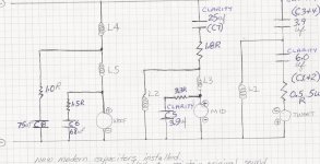
Not sure where you want them to go. Hopefully find a schematic of my xover here and be able to tell me what goes where.
_______________
Hi Doug,
it is good you included the Schematic drawn in your Post #608.
Where you have drawn the large O and written TWEET, connect the 27 ohm resistor there between the + and - points you marked.
Remove the 0.5R resistor and connect the 6.0uF capacitor directly to the - point marked there.
Where you have drawn the other large O and written MID, connect the 82 ohm there between the + and - points you marked.
NOTE: to other readers, about the 82 ohms:
(1) - this is for the MD500 version only at this stage of this discussion.
(2) - if you cannot obtain 82 ohms in 10 watt minimum in wirewound, then use 75 ohms or whatever value between 75 and 82 that you can find,
or use a Parallel connected pair of 5 watt wirewounds in 150 ohm or 160 ohm.
ALSO Doug,
as you have reported such low level of treble output, I think you should check the Continuity of all the circuit tracks and wires in the treble filters and to the tweeters.
Look at your crossover boards closely to see if any broken or loose circuit tracks, or small cracks in the tracks.
Check all wires to see if all their strands are connected, or if some are broken and only one or a few are intact.
Check the points where each component is soldered to the circuit track, and pull the component to test if the connection is firm.
If all the wires look OK, then with your multimeter, measure the ohms from one end to other end of each wire.
Resistance should be much lower than 1 ohm for every wire inside the enclosure.
***************
to WayneSwann and DennyG :
- I'll be back as soon as I have some more time available.
Last edited:
to sba - mods for MD500
Hi sba,
given all the interesting, and some very useful, measurements you have posted during two separate periods to date, and that I have used it to make calculations and estimations to advise some of the others in this Thread how to fine-tune their 66s, it really is past time when I should have posted something useful for you to try ... thus without further ado ...
Regarding the Distortion in that MD500:
(1) - can you identify which sample it is ?
Eg: which Colour Impedance plot and/or Frequency Response plot of those in # on Page * is it ?
(2) - if you measured your other MD500, is it similar/better/worse for Distortion ?
(3) - if you measured any of the MF500s for Distortion, how do they compare to that measured MD ?
Remember what tonedef2 posted about the internal damping of MD500 early in this Thread, and what he found both physically and audibly for substantially deteriorated samples.
Your deteriorated internally damped MD is the one you posted as the Purple impedance plot in #354 on Page 36 - which I will refer to as "2009 purple" - and that is also the Yellow impedance plot in #490 on Page 49 - which I will refer to as "2010 yellow".
Similarly, the less or little deteriorated MD is "2009 Dark green" = "2010 orange".
Given how the Reactances of the crossover components interact with the Impedance of the driver, and thus how the signal voltage is divided between the crossover and driver, there will be greater voltage across the 2010 yellow MD at its Fs than there is across the 2010 orange MD,
thus the yellow will be driven harder there and will be distorting more ... and especially so as it has less mechanical damping -
- refer to yout 2009 tabulated Q(ms) for both those drivers: 2009 purple versus 2009 Dark green.
This Higher Impedance at Fs of the lesser damped MD can be reduced via a resistor connected in Parallel with the driver.
Such resistance will lower the Impedance there, thus lower Voltage will be present there -{and greater voltage drop there in the crossover,
which is what is needed there}.
That is applying Electrical damping to compensate for the less good Mechanical damping.
Interruption: I am being logged Off here !
I will be back to complete this as soon as I have time available.
I will Proof-Read my Post then.
Here is some THD data. The distortion looks bad on the mid dome between 500-600hz
md500 mid dome
View attachment 179268
Hi sba,
given all the interesting, and some very useful, measurements you have posted during two separate periods to date, and that I have used it to make calculations and estimations to advise some of the others in this Thread how to fine-tune their 66s, it really is past time when I should have posted something useful for you to try ... thus without further ado ...
Regarding the Distortion in that MD500:
(1) - can you identify which sample it is ?
Eg: which Colour Impedance plot and/or Frequency Response plot of those in # on Page * is it ?
(2) - if you measured your other MD500, is it similar/better/worse for Distortion ?
(3) - if you measured any of the MF500s for Distortion, how do they compare to that measured MD ?
Remember what tonedef2 posted about the internal damping of MD500 early in this Thread, and what he found both physically and audibly for substantially deteriorated samples.
Your deteriorated internally damped MD is the one you posted as the Purple impedance plot in #354 on Page 36 - which I will refer to as "2009 purple" - and that is also the Yellow impedance plot in #490 on Page 49 - which I will refer to as "2010 yellow".
Similarly, the less or little deteriorated MD is "2009 Dark green" = "2010 orange".
Given how the Reactances of the crossover components interact with the Impedance of the driver, and thus how the signal voltage is divided between the crossover and driver, there will be greater voltage across the 2010 yellow MD at its Fs than there is across the 2010 orange MD,
thus the yellow will be driven harder there and will be distorting more ... and especially so as it has less mechanical damping -
- refer to yout 2009 tabulated Q(ms) for both those drivers: 2009 purple versus 2009 Dark green.
This Higher Impedance at Fs of the lesser damped MD can be reduced via a resistor connected in Parallel with the driver.
Such resistance will lower the Impedance there, thus lower Voltage will be present there -{and greater voltage drop there in the crossover,
which is what is needed there}.
That is applying Electrical damping to compensate for the less good Mechanical damping.
Interruption: I am being logged Off here !
I will be back to complete this as soon as I have time available.
I will Proof-Read my Post then.
Last edited:
Continuing - to sba - mods for MD500
.
I'm back, and on a different computer which I hope I can use for sufficient duration to get this finished.
continuing from my above Post:-
Yes, a Parallel connected resistor will cause lower Impedance across the entirety of the driver's bandwidth,
and FORTUNATELY in this case, because, notice that your other MD500 has a lower Impedance trace throughout the portion of its bandwidth that is being used for the wanted signal, thus with careful choice of resistor value you can have a closer impedance matched pair of MDs.
That will cause both to cross over at closer to the same frequencies as each other to the other drivers,
and for the 2010 yellow which has a slightly higher peak in output level at about 4.5kHz than 2010 orange -{ refer to #499 on Page 50}-
a closer match can be achieved there,
because the resistor-lowered Impedance for 2010 yellow will cause the .34mH inductor in the crossover to drop a little more of the signal there.
You will not get closer matching in the higher frequencies -{above 4.5kHz}- but you don't have that now ...
but because of the slightly lower Impedance of both MDs, {after this mod to one of them}, the actual cross-over point will be lower than 5 kHz.
With careful choice from your several samples of JBL tweeters, and some specific resistor treatment of those, you can likely get a fairly close to matched pair of 66s across the full spectrum.
{The bass drivers look less of a problem, and I'll comment further on those in a later post.}
What resistance value for this mod:
- considering the Standard E Series values for resistors, I think 82 ohms is the most likely to work best for a reasonable compromise between the requirements in the low mids versus in the high mids.
There will not be a lot of current passing through 82 ohms, but there will be significant voltage across it, because there is a lot of signal energy in the midrange of Music,
thus use at least a 10 watt wirewound resistor, because for non-interference with the signal it must be kept cool.
It does not need to be non-inductive in this application, but it does need to be of good quality materials and assembly so as to not couple electric results of mechanical faults into the mids' circuit,
thus of quality brands, I recommend you buy a well specified "Ohmite"
{from whichever of their ranges seems the best of those that are for sale from whoever}
or "Dale" -{now Vishay-Dale}- if no Ohmite, or a Mills MRA-12 .
"Well specified":- look for whichever model has the lowest specified Temperature Co-efficient {Temp-Co}, and lowest specified Voltage Co-efficient, and if "Pulse" rated.
If you want to experiment using a resistor you may already have before you buy, and don't have an 82 ohm, then 75 ohm in 10 watt will work as next best compromise.
I would not use lower than 68 ohm, because then the mid-band Impedance will be dropped too low and the crossover points will have shifted too much as result, plus you may have lost too much at 4.5kHz with even 68 ohm there.
With 100 ohm there may not be sufficient effect for audible improvement.
You can use a Parallel connected pair of 150 ohm or 160 ohm in 5 watt resistors there if you have such.
Connect the resistor across the midrange filter's Output on your board.
I think there will be plenty of space there on your own-made large boards !
Select a pair of tweeters that are very similar in measured frequency characteristics in their 5kHz <--> 10kHz region so that you will be hearing the effects the resistor causes on the treated MD, and not masked by differences between the tweeters.
***************
OK, that deals with matching a pair of MDs, but not with over-all distortion if the other MD has significant distortion ...
and if similar occurs in the MF500s.
Yes, Parallel connected resistors can be used with all the mid-domes,
and of lower resistances than 82 ohms to lower distortion even more at the low end, but you will lose more at the high end as result, and will shrink the mid-range bandwidth.
To not reduce bandwidth if you decide to resistor parallel all your mid-domes you will need to make L-pads:
using a suitable value small Series connected resistor between the top of the Parallel resistor and the junction point of the .34mH inductor and 3.9uF cap.
That will raise the Impedance seen by the crossover, though will lower the output of the mids a little, thus if you want to try that, Post and I will advise further,
but I recommend you listen first to the deteriorated MD paralleled by 82 ohms before you decide further.
Note:- if you measure the frequency response of that MD with 82 ohms connected in Parallel with it, there will not likely be any diffence visible on the plot.
To see any difference you will have to measure it when connected to the midrange filter of the crossover -
2 plots, both connected to the crossover filter, one with Parallel resistor and one without Parallel resistor.
Warning:
- connect Load Simulating resistors to the treble and bass outputs of the crossover before you send amplified measurement signal through that crossover.
4.7 ohms in 10 watts will be OK in both positions,
or even in 5 watts if you test with low voltage signals.
***************
Now, in 2009 you plotted Impedance for 6 samples of mid-domes:
#354 on Page 36.
{I correctly guessed one of the MDs then, but not the other !}
Of those, 2009-Yellow is likely faulty, but 2009-Blue seemed to be OK,
and likely in better condition than 2009-Orange.
Do you still have 2009-Blue ?
It is not amongst the 2010 Impedance plots.
I see in the 2010 plots that 2009-Orange is 2010-Purple, an MF500,
but as the two 2010 MF500 frequency response plots do not match,
perhaps 2009-Blue will be closer to the seeming lesser faulty 2009-Light green/2010-Blue MF, than the seeming faulty 2009-Orange/2010-Purple is.
Do you have any Frequency Response plot for 2009-Blue ? ...
or a reason for not including it ?
***************
I'll comment about ideas for applications of your MF500s later,
and I have some ideas for you about the tweeters also,
but no more time today to proceed with those unfortunately.
.
I'm back, and on a different computer which I hope I can use for sufficient duration to get this finished.
(1) - can you identify which sample it is ?
Eg: which Colour Impedance plot and/or Frequency Response plot of those in # 490 on Page 49 is it ?
EDIT: --- it seems to be for the 2009 purple/2010 yellow - that is the greater deteriorated sample.
Questions (2) and (3) still stand - any measurements for those ?
***************
- refer to yout 2009 tabulated Q(ms) for both those drivers: 2009 purple versus 2009 Dark green.
EDIT: - to correct spelling of "yout" to "your" !
{this is not my native pronunciation accent}.
.
continuing from my above Post:-
Yes, a Parallel connected resistor will cause lower Impedance across the entirety of the driver's bandwidth,
and FORTUNATELY in this case, because, notice that your other MD500 has a lower Impedance trace throughout the portion of its bandwidth that is being used for the wanted signal, thus with careful choice of resistor value you can have a closer impedance matched pair of MDs.
That will cause both to cross over at closer to the same frequencies as each other to the other drivers,
and for the 2010 yellow which has a slightly higher peak in output level at about 4.5kHz than 2010 orange -{ refer to #499 on Page 50}-
a closer match can be achieved there,
because the resistor-lowered Impedance for 2010 yellow will cause the .34mH inductor in the crossover to drop a little more of the signal there.
You will not get closer matching in the higher frequencies -{above 4.5kHz}- but you don't have that now ...
but because of the slightly lower Impedance of both MDs, {after this mod to one of them}, the actual cross-over point will be lower than 5 kHz.
With careful choice from your several samples of JBL tweeters, and some specific resistor treatment of those, you can likely get a fairly close to matched pair of 66s across the full spectrum.
{The bass drivers look less of a problem, and I'll comment further on those in a later post.}
What resistance value for this mod:
- considering the Standard E Series values for resistors, I think 82 ohms is the most likely to work best for a reasonable compromise between the requirements in the low mids versus in the high mids.
There will not be a lot of current passing through 82 ohms, but there will be significant voltage across it, because there is a lot of signal energy in the midrange of Music,
thus use at least a 10 watt wirewound resistor, because for non-interference with the signal it must be kept cool.
It does not need to be non-inductive in this application, but it does need to be of good quality materials and assembly so as to not couple electric results of mechanical faults into the mids' circuit,
thus of quality brands, I recommend you buy a well specified "Ohmite"
{from whichever of their ranges seems the best of those that are for sale from whoever}
or "Dale" -{now Vishay-Dale}- if no Ohmite, or a Mills MRA-12 .
"Well specified":- look for whichever model has the lowest specified Temperature Co-efficient {Temp-Co}, and lowest specified Voltage Co-efficient, and if "Pulse" rated.
If you want to experiment using a resistor you may already have before you buy, and don't have an 82 ohm, then 75 ohm in 10 watt will work as next best compromise.
I would not use lower than 68 ohm, because then the mid-band Impedance will be dropped too low and the crossover points will have shifted too much as result, plus you may have lost too much at 4.5kHz with even 68 ohm there.
With 100 ohm there may not be sufficient effect for audible improvement.
You can use a Parallel connected pair of 150 ohm or 160 ohm in 5 watt resistors there if you have such.
Connect the resistor across the midrange filter's Output on your board.
I think there will be plenty of space there on your own-made large boards !
Select a pair of tweeters that are very similar in measured frequency characteristics in their 5kHz <--> 10kHz region so that you will be hearing the effects the resistor causes on the treated MD, and not masked by differences between the tweeters.
***************
OK, that deals with matching a pair of MDs, but not with over-all distortion if the other MD has significant distortion ...
and if similar occurs in the MF500s.
Yes, Parallel connected resistors can be used with all the mid-domes,
and of lower resistances than 82 ohms to lower distortion even more at the low end, but you will lose more at the high end as result, and will shrink the mid-range bandwidth.
To not reduce bandwidth if you decide to resistor parallel all your mid-domes you will need to make L-pads:
using a suitable value small Series connected resistor between the top of the Parallel resistor and the junction point of the .34mH inductor and 3.9uF cap.
That will raise the Impedance seen by the crossover, though will lower the output of the mids a little, thus if you want to try that, Post and I will advise further,
but I recommend you listen first to the deteriorated MD paralleled by 82 ohms before you decide further.
Note:- if you measure the frequency response of that MD with 82 ohms connected in Parallel with it, there will not likely be any diffence visible on the plot.
To see any difference you will have to measure it when connected to the midrange filter of the crossover -
2 plots, both connected to the crossover filter, one with Parallel resistor and one without Parallel resistor.
Warning:
- connect Load Simulating resistors to the treble and bass outputs of the crossover before you send amplified measurement signal through that crossover.
4.7 ohms in 10 watts will be OK in both positions,
or even in 5 watts if you test with low voltage signals.
***************
Now, in 2009 you plotted Impedance for 6 samples of mid-domes:
#354 on Page 36.
{I correctly guessed one of the MDs then, but not the other !}
Of those, 2009-Yellow is likely faulty, but 2009-Blue seemed to be OK,
and likely in better condition than 2009-Orange.
Do you still have 2009-Blue ?
It is not amongst the 2010 Impedance plots.
I see in the 2010 plots that 2009-Orange is 2010-Purple, an MF500,
but as the two 2010 MF500 frequency response plots do not match,
perhaps 2009-Blue will be closer to the seeming lesser faulty 2009-Light green/2010-Blue MF, than the seeming faulty 2009-Orange/2010-Purple is.
Do you have any Frequency Response plot for 2009-Blue ? ...
or a reason for not including it ?
***************
I'll comment about ideas for applications of your MF500s later,
and I have some ideas for you about the tweeters also,
but no more time today to proceed with those unfortunately.
Hi sba,
Given how the Reactances of the crossover components interact with the Impedance of the driver, and thus how the signal voltage is divided between the crossover and driver, there will be greater voltage across MD at its Fs than there is across the 2010 orange MD,
thus the yellow will be driven harder there and will be distorting more ... and especially so as it has less mechanical damping...
This Higher Impedance at Fs of the lesser damped MD can be reduced via a resistor connected in Parallel with the driver.
Such resistance will lower the Impedance there, thus lower Voltage will be present there -{and greater voltage drop there in the crossover,
which is what is needed there}.
That is applying Electrical damping to compensate for the less good Mechanical damping...
a Parallel connected resistor will cause lower Impedance across the entirety of the driver's bandwidth,
and FORTUNATELY in this case, because, notice that your other MD500 has a lower Impedance trace throughout the portion of its bandwidth that is being used for the wanted signal, thus with careful choice of resistor value you can have a closer impedance matched pair of MDs.
That will cause both to cross over at closer to the same frequencies as each other to the other drivers,
and for the 2010 yellow which has a slightly higher peak in output level at about 4.5kHz than 2010 orange -{ refer to #499 on Page 50}-
a closer match can be achieved there,
because the resistor-lowered Impedance for 2010 yellow will cause the .34mH inductor in the crossover to drop a little more of the signal there...
OK, that deals with matching a pair of MDs, but not with over-all distortion if the other MD has significant distortion ...
and if similar occurs in the MF500s.
Yes, Parallel connected resistors can be used with all the mid-domes,
and of lower resistances than 82 ohms to lower distortion even more at the low end, but you will lose more at the high end as result, and will shrink the mid-range bandwidth.
To not reduce bandwidth if you decide to resistor parallel all your mid-domes you will need to make L-pads:
using a suitable value small Series connected resistor between the top of the Parallel resistor and the junction point of the .34mH inductor and 3.9uF cap.
That will raise the Impedance seen by the crossover, though will lower the output of the mids a little, thus if you want to try that, Post and I will advise further,
but I recommend you listen first to the deteriorated MD paralleled by 82 ohms before you decide further.
Alan,
That’s an insightful and clever solution !
Prior to any alterations I want to re-measure the speakers. As you might recall, after posting the plots, I discovered an anomaly in the impulse response that effects the resolution of the FR.
And not reported ‘till now… While trying to solve that problem I found another. The mic’s phantom power supply / preamp (a Behringer tube mic100) was creating a significant amount of distortion. At least that’s what the audio analyser program indicated when I expanded a test beyond just the soundcard and included the cables, connectors, and finally the mic preamp itself into the in-out measuring loop.
After a lot of investigation I still don’t know the cause of the original problem, but a new soundcard installed on a different computer seems to work okay, so I‘ll use that setup. For the distortion problem I replaced the Behringer with a Rolls MP13 mic preamp, which also seems to work okay.
I don’t expect any major surprises from re-measuring, just perhaps a little more detail and accuracy. I also wonder how much the Behringer effected the distortion measurements. We’ll see! It was reassuring to see Celestion’s B&K plot.
if you measure the frequency response of that MD with 82 ohms connected in Parallel with it, there will not likely be any diffence visible on the plot.
To see any difference you will have to measure it when connected to the midrange filter of the crossover -
2 plots, both connected to the crossover filter, one with Parallel resistor and one without Parallel resistor.
Warning:
- connect Load Simulating resistors to the treble and bass outputs of the crossover before you send amplified measurement signal through that crossover.
4.7 ohms in 10 watts will be OK in both positions,
or even in 5 watts if you test with low voltage signals.
I'll try this.
****************************
Here’s some of the data you were wondering about. The colors here are synced to the original impedance plot, post #394.
I have two remaining md 500s (green & purple), and two mf 500s (green & orange). The other two mf 500s, (yellow & blue) were traded away.


Hi,
I've recently purchased a pair of Celestion ditton 662 speakers, one of the tweeters was dead and a replacement is on it's way. I used to have access to a pair of ditton 44s and these definitely seem like a big step up from those, overall I'm very pleased with them despite the blown tweeter.
The good speaker sounds utterly amazing and all the other drivers sound fantastic, I was considering recapping the crossovers and was curious if anyone knows what the crossover frequencies are or better yet has an accurate schematic for the things?
I was also wondering if anyone could recommend something to put the speakers on? At the moment they're just sitting on floorboards, I have spikes but can't use them as it's a rented house.
I also welcome any other suggestions as to how to improve these lovely speakers, they're in wonderful condition with barely a mark on them and they seem to get on well with the amp that I have.
It would also be appreciated if anyone could recommend some capacitors, I've skimmed the 66 needs midrange thread though most of the caps I've seen are only available in the US unfortunately.
I've recently taken a HF2001 tweeter apart and the dome shape and material appears to be identical to the HF2000, as does the permanent magnet behind. The main differences seem to be how the dome is attached to the speaker, with the HF2000 it's just stuck on with a ring of tape, with the HF2001 it's clamped down and held with a large ring double sided tape under a solid piece that holds it all together. The build quality is also a lot better with the HF2001, while the HF2000 looked messy and almost crude all the coatings on the HF2001 look evenly applied.
The coil also appears to be arranged slightly tighter and in a very slightly further back position under the dome.
http://www.btinternet.com/~david.ste.../IMG_13781.jpg
As compared to that the coil is thinner and positioned higher up along the edge.
The reason I took apart my HF2001 is that it was completely dead, the coil was utterly fried so I unwound it and measured it, 28 turns of 40 awg wire measuring 192cm terminal to terminal. due to the design of the HF2001 it would be very easy to construct a jig to attach the thing to a hand drill so I've ordered some replacement wire and I fully intend to have a crack at re-winding the thing.
If anyone is interested I'll happily post some pictures tomorrow some time, I'll definitely write up the repair once it's done too.
Hi SatinMill,
I thought I had downloaded a 662 schematic, but I can't find anywhere. I'll keep looking.
- Status
- This old topic is closed. If you want to reopen this topic, contact a moderator using the "Report Post" button.
- Home
- Loudspeakers
- Multi-Way
- Celestion 66 needs mid-range