TMC (thus not ETMC)
A few more remarks:
If you really think the ratio doesn't matter (as long as blah blah) just try (read: sim) 5:1 instead of 1:5, i.e. C3=620pF, C4=130pF and R12 = 1k7.
Notice that the transition frequency* is defined by C4 and R12, that is, if the gain of the OPS is exactly unity. In reality the gain will be lower, hence this frequency will be lower too.
Now let's go back to more serious cases. If C3=C4=220pF and R12=1k, as proposed by D.Self, then THD20k = 16.5ppm and SR = 26V/us
If C3=130pF, C4=620p and R12=360, as proposed by me, then THD20k = 8.8ppm and SR = 46V/us. I think these figures speak for itself. (The ULG frequency and transition frequency are kept the same as in the previous case)
I would almost say that D. Self has given TMC a bad reputation.
@Jan, what about a peer-review, next time?
* This is the frequency where the currents through C4 and R12 are equal in magnitude.
PS: Sims are based on the schematic as posted on page 3002 and the 'E part' has been disabled (C2=0).
There is no reason why the capacitors should be in the ratio of 1:5.
All that is required is that they should be selected to give the desired unity gain frequency. In otherwords, select the capacitor values as you would for double pole compensation.
The resistor is then selected to give the zero necesary to cancel the pole in the minor loop's transmission before its unity gain crossing.
A few more remarks:
If you really think the ratio doesn't matter (as long as blah blah) just try (read: sim) 5:1 instead of 1:5, i.e. C3=620pF, C4=130pF and R12 = 1k7.
Notice that the transition frequency* is defined by C4 and R12, that is, if the gain of the OPS is exactly unity. In reality the gain will be lower, hence this frequency will be lower too.
Now let's go back to more serious cases. If C3=C4=220pF and R12=1k, as proposed by D.Self, then THD20k = 16.5ppm and SR = 26V/us
If C3=130pF, C4=620p and R12=360, as proposed by me, then THD20k = 8.8ppm and SR = 46V/us. I think these figures speak for itself. (The ULG frequency and transition frequency are kept the same as in the previous case)
I would almost say that D. Self has given TMC a bad reputation.
@Jan, what about a peer-review, next time?
* This is the frequency where the currents through C4 and R12 are equal in magnitude.
PS: Sims are based on the schematic as posted on page 3002 and the 'E part' has been disabled (C2=0).
The history of TMC
Hi Bob, Jan & Gareth,
The funny and/or weird thing is that D. Self has also tried TMC somewhere in the nineties and has told me that the results were not exciting. Together with the fact that he has published an implementation of TMC that is far from optimal and poorly reflects the rationale behind the idea, and the fact that we have never seen a publication by Baxandall on this subject, I'm seriously asking myself whether Baxandall's circuit, to which D. Self referred, was indeed TMC. In any case, I have reason to believe that it was not the circuit as intended by me. (that means: C2 >> C1, but C2 not that large and accordingly Ri that small, such that the input and output of the OPS virtually is shunted)
Cheers,
E.
Unfortunately, Doug did not mention explicitly in his article that the technique has been explored at length here (starting at least three years ago),
.............
Cheers,
Bob
Doug Self refers to it as 'Private Communication, 1995'. Personally, I've never seen any published writing by Baxandall on TMC.
jan didden
Interesting, I remember reading a comment from D. Self that he was looking at a compensation technique that partially included the output stage, that the results were very good ......................
Here's the quote:
".... I have recently done some work that shows it is possible to partly include the output stage in the Miller loop, and it does give significant advantages in normal operation. This is a rather exciting development, but still under study and I am not ready to disclose it..."
...............
Hi Bob, Jan & Gareth,
The funny and/or weird thing is that D. Self has also tried TMC somewhere in the nineties and has told me that the results were not exciting. Together with the fact that he has published an implementation of TMC that is far from optimal and poorly reflects the rationale behind the idea, and the fact that we have never seen a publication by Baxandall on this subject, I'm seriously asking myself whether Baxandall's circuit, to which D. Self referred, was indeed TMC. In any case, I have reason to believe that it was not the circuit as intended by me. (that means: C2 >> C1, but C2 not that large and accordingly Ri that small, such that the input and output of the OPS virtually is shunted)
Cheers,
E.
Hi Edmond,
I agree with your observation, and indeed would love to have seen any writings of Baxandall on the subject. That would make it possible to see if it really was a proper example of TMC that he was discussing.
In any case, we know that TMC is indeed very effective, and hopefully the more accurate discussion of it in my book will undo any damage that was done to TMC's reputation.
Cheers,
Bob
Hi Edmond,
I agree with your observation, and indeed would love to have seen any writings of Baxandall on the subject. That would make it possible to see if it really was a proper example of TMC that he was discussing.
Maybe D. Self is kind enough to drop a copy of Baxandall's analysis on this forum.
In any case, we know that TMC is indeed very effective, and hopefully the more accurate discussion of it in my book will undo any damage that was done to TMC's reputation.
Cheers,
Bob
Hi Bob,
I'm sure it does. Your treatise on this subject is correct and very to the point.
Cheers,
E.
edit PS: As you probably understood already, I received your book last week. I like to comment on it (probably only minor things), though it will take some time to thoroughly read some 600 pages of your opus magnum.
Last edited:
Okay, no problem. Here's a copy of the first post from 'over there':
"As a present for this new audio forum I'll give away my latest secret.
As you all already know, TMC stands for Transitional Miller Compensation. The preceding E is new and stands for Error correction (or Extended). Just like TMC (and HEC!), it only reduces the distortion produced by the output stage. This means that to be effective, all other stage must be perfect (well, almost). Additionally, the input impedance of the OPS should also as high as possible, otherwise this trick simply doesn't work. So you will be warned.
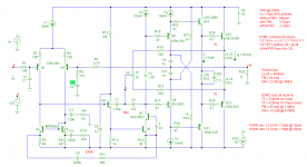
Here's a simple implementation on a basic amplifier: see pic below.
The TMC respectively [additional] ETMC components are encircled*. As you see, this error correction scheme uses only one extra active component (Q5) and a few passive ones. If applied to an amp with a common mode control loop (CMCL), then the active components are already there and only two additional C's and R's are needed.
The result (see schematic text) speaks for itself. If I have more time (next week) I'll elaborate on this topic and answer questions.
Cheers,
Edmond."
* So the complete ETMC circuit comprises both encircled components.
NB: This information may not be published in part or whole (either on-line or in print) without written permission of the author.
IOW, no more hijacking of my ideas, please!
What about tiyng the collector of the Q5 to the positive source rail ? Frankly said, I don't like if the earth is internally involved anywhere else than at powering, input and the FB's reference point. Of course, in such case the eventual signal residua on the positive supply rail can leak into the ETMC way, but it can be overcame by cascoding or so...

It seems to me that Gunderson's cascode:
http://www.diyaudio.com/forums/solid-state/83222-gunderson-compensation-2.html#post963035
achieves similar results to the TMC approach. By just copying the output voltage back to the VAS collector(s), for use by the Miller compensation. Maybe Baxandall came up with TMC as a workaround of Gunderson's patent back in 1985 (# 4,511,857).
It was also mentioned that Slone had come up with some new crossover distortion approach recently (I think it came up in Bob's book thread), and Slone already used a similar (but not exactly the same) setup as Gunderson in his Optimos Amplifier. Maybe Slone moved his compensation network over to the cascode emitter position, like Gunderson.
In any case, for TMC or Gunderson, another (apparently patented a few times) crossover fixup scheme comes to mind as an easy add-on. I first saw this mentioned by Brodskie on his TubeCad blog:
European Triode Festival and Crossover Notch Distortion and New OTL Design
(2nd diagram up from the bottom)
In trying to locate that patent (which I never could) a few similar patents came up, using the same two resistor network feedback pickoff from the output device emitters/sources (one set of the dual 100 Ohm resistors in the tubecad schematic). This crossover enhanced pickoff signal was then used to operate an output drive correction stage, similar to HEC using the Vbe multiplier.
It seems to me that one might put a pot (say 100 Ohm maybe) between the crossover pickup node ( the 100 Ohm resistors tie point) and the actual amplifier output (well, the tie point of the typical 0.1 Ohm emitter/source resistors). Then take the pot wiper back to either the TMC network resistor(s) or the Gunderson cascode base terminal(s). Then adjust the pot till the crossover distortion nulls to a minimum. Something of an enhanced crossover error feedback, which would require then only finite loop gain.
Don B.
Do you mean tying the collector of the Q5 directly to the positive rail or via R7?
Of course, the R7 must remain at place ...
 - and the cascoding is meant so that the the R7 would be connected to the emiter of a NPN BJT or source of N-FET instead of to the earth, the base (or gate) of the cascoding element being connected to the earth and collector (or drain respectively) to the positive supply rail. This way the collector current of the Q5 would be separated from the earth and the influence of the variations of the positive supply voltage would be eliminated.
In general, the ETMC seems to be a good trick, but also it seems to be raising the speed of the open loop in general, thus being a little bit dangerous for the closed loop stability IMHO (I didn't make the simulation nor mathematical analysis - this is a "first glance impression" only indeed
basing on my experience with the "lead compensation" according Otala many years ago).ETMC
You didn't say that. Besides, as the majority of the people around here doesn't understand even TMC, how could I know if this was so obvious to you?
Indeed, that would be a possibility. Whether a cascode is really necessary depends on several factors, including PCB lay-out or even someone's personal taste. For the same reason I assume that you also have issues with the collector of Q6.
I don't see a direct connection to Otala's lead compensation, though I agree with you that the stability is affected (a little bit). As I already said (see post 3011), any arrangement of error feedback will impair the stability.
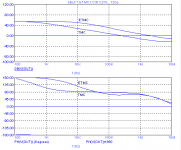
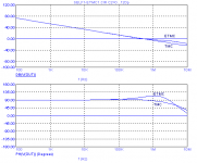
In case of ETMC, the BW of the local FB loop (via R12) is indeed increased, see 1st pic below. So the circuitry around this loop does need careful attention (base stopper etc.). The global FB loop however is almost unchanged, i.e. same ULGF and slightly higher phase margin. See 2nd pic.
Disclaimer. The schematic as shown on page 3002, depicts only the basic principle. It's far from complete. If built without the utmost care to potential pitfalls, it will certainly oscillate.
Of course, the R7 must remain at place ...
You didn't say that. Besides, as the majority of the people around here doesn't understand even TMC, how could I know if this was so obvious to you?
- and the cascoding is meant so that the the R7 would be connected to the emiter of a NPN BJT or source of N-FET instead of to the earth, the base (or gate) of the cascoding element being connected to the earth and collector (or drain respectively) to the positive supply rail. This way the collector current of the Q5 would be separated from the earth and the influence of the variations of the positive supply voltage would be eliminated.
Indeed, that would be a possibility. Whether a cascode is really necessary depends on several factors, including PCB lay-out or even someone's personal taste. For the same reason I assume that you also have issues with the collector of Q6.
In general, the ETMC seems to be a good trick, but also it seems to be raising the speed of the open loop in general, thus being a little bit dangerous for the closed loop stability IMHO (I didn't make the simulation nor mathematical analysis - this is a "first glance impression" only indeed
I don't see a direct connection to Otala's lead compensation, though I agree with you that the stability is affected (a little bit). As I already said (see post 3011), any arrangement of error feedback will impair the stability.
In case of ETMC, the BW of the local FB loop (via R12) is indeed increased, see 1st pic below. So the circuitry around this loop does need careful attention (base stopper etc.). The global FB loop however is almost unchanged, i.e. same ULGF and slightly higher phase margin. See 2nd pic.
Disclaimer. The schematic as shown on page 3002, depicts only the basic principle. It's far from complete. If built without the utmost care to potential pitfalls, it will certainly oscillate.
Attachments
Alt-ETMC
What about deleting Q5 altogether?
Here's an alternative approach of ETMC, courtesy of Dimitri who co-invented this mod.
All 'unnecessary' connections to gnd have been eliminated, except R9, as this one has to be tied to gnd.
As for the positive FB loop, now the signal is taken directly from the VAS emitter and fed to the emitter of Q2. This mod saves one tranny, though at the cost of two more C's and R's.
In the meantime I've also add some more base stoppers and modified the diamond buffer. This version is less prone to oscillations. The TMC resistor, originally tied to the output, has been replaced by two resistors (R15 & R18) tied to the emitters of the OPS. As a result, the TMC transition frequency is (slightly) less dependent on the output load. With these two resistors already available, I couldn't resist the temptation to also add my magic tinny pot (P1). Does anybody remember what it is for? Hint: it can save you a PCB re-design !!!
C4 and R10 restore the CMRR of the IPS (which was disturbed by C5 & R11).
For more details, see the text inside the schematic.
Cheers,
E.
@Jan: With this example, I hope it's getting clear that the improvement in PSRR is no specific feature of ETMC, rather a feature of C3 & R9 (in the previous schematic C2 & R8, which just happens to be also part of the ETMC stuff)
>What about tying the collector of the Q5 ....What about tiyng the collector of the Q5 to the positive source rail ? Frankly said, I don't like if the earth is internally involved anywhere else than at powering, input and the FB's reference point. Of course, in such case the eventual signal residua on the positive supply rail can leak into the ETMC way, but it can be overcame by cascoding or so...
What about deleting Q5 altogether?
Here's an alternative approach of ETMC, courtesy of Dimitri who co-invented this mod.
All 'unnecessary' connections to gnd have been eliminated, except R9, as this one has to be tied to gnd.
As for the positive FB loop, now the signal is taken directly from the VAS emitter and fed to the emitter of Q2. This mod saves one tranny, though at the cost of two more C's and R's.
In the meantime I've also add some more base stoppers and modified the diamond buffer. This version is less prone to oscillations. The TMC resistor, originally tied to the output, has been replaced by two resistors (R15 & R18) tied to the emitters of the OPS. As a result, the TMC transition frequency is (slightly) less dependent on the output load. With these two resistors already available, I couldn't resist the temptation to also add my magic tinny pot (P1). Does anybody remember what it is for? Hint: it can save you a PCB re-design !!!
C4 and R10 restore the CMRR of the IPS (which was disturbed by C5 & R11).
For more details, see the text inside the schematic.
Cheers,
E.
@Jan: With this example, I hope it's getting clear that the improvement in PSRR is no specific feature of ETMC, rather a feature of C3 & R9 (in the previous schematic C2 & R8, which just happens to be also part of the ETMC stuff)
Attachments
Edmond:
"The TMC resistor, originally tied to the output, has been replaced by two resistors (R15 & R18) tied to the emitters of the OPS. As a result, the TMC transition frequency is (slightly) less dependent on the output load. With these two resistors already available, I couldn't resist the temptation to also add my magic tinny pot (P1). Does anybody remember what it is for? Hint: it can save you a PCB re-design !!!"
Has this been discussed before? Where can I find the posts?
It's not quite the same setup I envisioned a few posts above, expecting only a small amount of this enhanced crossover feedback to be needed to null the crossover dist. I expected a pot between a junction of R18 and R15 (instead of P1 in series) and the OUT point.
Don B.
"I couldn't resist the temptation to also add my magic tinny pot (P1). Does anybody remember what it is for? Hint: it can save you a PCB re-design !!!"
Obviously P1 allows for fixing any mismatch of R26 and R27 tolerances as well as Q12 and Q13 gm mismatch (hmm, maybe not so well for gm mismatch, global FDBK will have to handle most of that one).
But it doesn't allow control of the amount of current feedback mixed in with the voltage feedback. For that you would still need a pot P2 from the P1 wiper to the "OUT" terminal, then the wiper of P2 would provide the TMC pickoff. And then a resistor in series with that pickoff for the TMC RC time constant setting, unless the POTs and R18/R15 were allready set up to give the correct resistance equivalent.
Some reason that the current feedback portion is max'd out?
Don B.
Last edited:
Obviously P1 allows for fixing any mismatch of R26 and R27 tolerances as well as Q12 and Q13 gm mismatch.
No, this is for balancing mutual inductive influence from rail loops to the loudspeaker wire/trace.
The most insidious distotion.
Hi Don,
Regarding P1, Please see: http://www.diyaudio.com/forums/soli...-interview-bjt-vs-mosfet-121.html#post1207205 , 2nd paragraph.
Cheers,
E.
Hi Don,
Regarding P1, Please see: http://www.diyaudio.com/forums/soli...-interview-bjt-vs-mosfet-121.html#post1207205 , 2nd paragraph.
Cheers,
E.
No, this is for balancing mutual inductive influence from rail loops to the loudspeaker wire/trace.
Exactly !!!
Cheers,
E.
- Home
- Amplifiers
- Solid State
- Bob Cordell Interview: Negative Feedback