I want to have also that papers.
about the term
"Transitional Miller Compensation" (TMC) isn't to find a lot, only few URLs::
ETMC, A Novel Error Correction Method
post 29 about
http://www.diyaudio.com/forums/soli...feedback-how-realy-works-some-examples-3.html
Hi tiefbassuebertr,
Perhaps Edmond could put a version of that post (ETMC) up on this thread for us to see.
Cheers,
Bob
ETMC
Okay, no problem. Here's a copy of the first post from 'over there':
"As a present for this new audio forum I'll give away my latest secret.
As you all already know, TMC stands for Transitional Miller Compensation. The preceding E is new and stands for Error correction (or Extended). Just like TMC (and HEC!), it only reduces the distortion produced by the output stage. This means that to be effective, all other stage must be perfect (well, almost). Additionally, the input impedance of the OPS should also as high as possible, otherwise this trick simply doesn't work. So you will be warned.
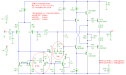
Here's a simple implementation on a basic amplifier: see pic below.
The TMC respectively [additional] ETMC components are encircled*. As you see, this error correction scheme uses only one extra active component (Q5) and a few passive ones. If applied to an amp with a common mode control loop (CMCL), then the active components are already there and only two additional C's and R's are needed.
The result (see schematic text) speaks for itself. If I have more time (next week) I'll elaborate on this topic and answer questions.
Cheers,
Edmond."
* So the complete ETMC circuit comprises both encircled components.
NB: This information may not be published in part or whole (either on-line or in print) without written permission of the author.
IOW, no more hijacking of my ideas, please!
Hi tiefbassuebertr,
Perhaps Edmond could put a version of that post (ETMC) up on this thread for us to see.
Cheers,
Bob
Okay, no problem. Here's a copy of the first post from 'over there':
"As a present for this new audio forum I'll give away my latest secret.
As you all already know, TMC stands for Transitional Miller Compensation. The preceding E is new and stands for Error correction (or Extended). Just like TMC (and HEC!), it only reduces the distortion produced by the output stage. This means that to be effective, all other stage must be perfect (well, almost). Additionally, the input impedance of the OPS should also as high as possible, otherwise this trick simply doesn't work. So you will be warned.
Here's a simple implementation on a basic amplifier: see pic below.
The TMC respectively [additional] ETMC components are encircled*. As you see, this error correction scheme uses only one extra active component (Q5) and a few passive ones. If applied to an amp with a common mode control loop (CMCL), then the active components are already there and only two additional C's and R's are needed.
The result (see schematic text) speaks for itself. If I have more time (next week) I'll elaborate on this topic and answer questions.
Cheers,
Edmond."
* So the complete ETMC circuit comprises both encircled components.
NB: This information may not be published in part or whole (either on-line or in print) without written permission of the author.
IOW, no more hijacking of my ideas, please!
Attachments
Hi forr,
Yes, Baxandall did a lot. If anyone here has a specific reference in Baxandall's writings where he discussed or proposed TMC, please let me know.
Cheers,
Bob
I'd guess that you already have this six part series by Baxandall but I'm not sure if it covers TMC as I've not reread it since it came out:
http://www.diy-audio-engineering.org/index.php?topic=196.msg2885#msg2885
Rereading it now and will keep an eye out for TMC.
ETMC, a litle bit of math
And here another copy from 'over there':
Hi guys,
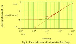
Finally, after many interruptions, here's a second attempt to calculate the FB loop gain. I hope it will make more sense now and make clear that under certain conditions the gain reaches infinity.
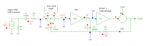
Below a block diagram of the most essential parts of the ETMC circuit:
For the sake of simplicity, as before, a lot of assumptions have been made:
1. An ideal VAS with infinite gain, infinite input impedance and output impedance.
2. An OPS with an infinite input impedance and a gain of 1.
3. Zero input signal, but a non-zero error signal, i.e Vfb != 0.
4. R3 and the VAS emitter degeneration R are set to zero.
5. Furthermore:
define s = j . 2 . pi . f
define t1 = C1.R1
define t2 = C2.R2
Because the VAS gain is infinite:
i1 + i2 = 0 or i2 = -i1
From ETMC, A Novel Error Correction Method equ (1) we now already:
i1 = i2.s.t1 / ( 1 + s.t1 ) and i2 = -i2.s.t1 / ( 1 + s.t1 )
i4 = i3 + i2
i4 = i3.(1 - s.t1 / (1 + s.t1) ) = i3 / (1 + s.t1 )
or i3 = i4 . (1 + s.t1 )
i2 = i4 - i3 = i4.( 1 - 1 - s.t1 ) = -i4.s.t1
Vn = i2 / ( s.C2 )
Vn = -i4.s.t1 / ( s.C2 ) = -i4.t1 / C2
i4 = ( Vfb - Vn ) / R2 = Vfb / R2 + i4.t1 / ( C2.R2 )
since t2 = C2.R2, we get
i4 = Vfb / R2 + i4 . t1 / t2
i4 ( 1 - t1 / t2 ) = Vfb / R2
i4 = Vfb / R2 . t2 / ( t1 - t2 ) = Vfb . C2 / ( t1 - t2 )
At this point it's already clear that if t1 = t2, then loop gain reaches infinity. Yet I will finish the derivation of Va = f(Vfb).
Va = Vn - i3 / ( s.C3 )
Va = -i4.t1 / C2 - i4.( 1 + s.t1 ) / ( s.C3 )
Va = -i4. ( t1 / C2 + ( 1 + s.t1 ) / ( s.C3 ) )
Va = -Vfb . C2 / ( t1 - t2 ). ( t1 / C2 + ( 1 + s.t1 ) / ( s.C3 ) )
Va = -Vfb.( t1 + C2.( 1 + s.t1 ) / ( s.C3 ) ) / ( t2 - t1 )
If t1 = t2, then Va/Vfb -> -infinity.
IOW, errors introduced by the output stage will be reduced to (almost) zero.
Cheers,
Edmond.
And here another copy from 'over there':
Hi guys,
Finally, after many interruptions, here's a second attempt to calculate the FB loop gain. I hope it will make more sense now and make clear that under certain conditions the gain reaches infinity.
Below a block diagram of the most essential parts of the ETMC circuit:
For the sake of simplicity, as before, a lot of assumptions have been made:
1. An ideal VAS with infinite gain, infinite input impedance and output impedance.
2. An OPS with an infinite input impedance and a gain of 1.
3. Zero input signal, but a non-zero error signal, i.e Vfb != 0.
4. R3 and the VAS emitter degeneration R are set to zero.
5. Furthermore:
define s = j . 2 . pi . f
define t1 = C1.R1
define t2 = C2.R2
Because the VAS gain is infinite:
i1 + i2 = 0 or i2 = -i1
From ETMC, A Novel Error Correction Method equ (1) we now already:
i1 = i2.s.t1 / ( 1 + s.t1 ) and i2 = -i2.s.t1 / ( 1 + s.t1 )
i4 = i3 + i2
i4 = i3.(1 - s.t1 / (1 + s.t1) ) = i3 / (1 + s.t1 )
or i3 = i4 . (1 + s.t1 )
i2 = i4 - i3 = i4.( 1 - 1 - s.t1 ) = -i4.s.t1
Vn = i2 / ( s.C2 )
Vn = -i4.s.t1 / ( s.C2 ) = -i4.t1 / C2
i4 = ( Vfb - Vn ) / R2 = Vfb / R2 + i4.t1 / ( C2.R2 )
since t2 = C2.R2, we get
i4 = Vfb / R2 + i4 . t1 / t2
i4 ( 1 - t1 / t2 ) = Vfb / R2
i4 = Vfb / R2 . t2 / ( t1 - t2 ) = Vfb . C2 / ( t1 - t2 )
At this point it's already clear that if t1 = t2, then loop gain reaches infinity. Yet I will finish the derivation of Va = f(Vfb).
Va = Vn - i3 / ( s.C3 )
Va = -i4.t1 / C2 - i4.( 1 + s.t1 ) / ( s.C3 )
Va = -i4. ( t1 / C2 + ( 1 + s.t1 ) / ( s.C3 ) )
Va = -Vfb . C2 / ( t1 - t2 ). ( t1 / C2 + ( 1 + s.t1 ) / ( s.C3 ) )
Va = -Vfb.( t1 + C2.( 1 + s.t1 ) / ( s.C3 ) ) / ( t2 - t1 )
If t1 = t2, then Va/Vfb -> -infinity.
IOW, errors introduced by the output stage will be reduced to (almost) zero.
Cheers,
Edmond.
Attachments
ETMC
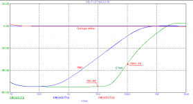
Another graph 'recovered' from 'over there'. It represents the additional distortion reduction as a function of frequency, obtained by TMC, respectively ETMC.
BTW, this is the reciprocal of the additional loop gain provided by TMC resp. ETMC.
So the 5th harmonic of a 20kHz sine, for example, will be further reduced by 34dB (compared to ordinary Miller compensation)
Cheers,
E.
Attachments
Mike,
Welcome back.
Cheers,
Bob
Thanks bob. I look forward to reading your book.
")
Okay, no problem. Here's a copy of the first post from 'over there':
"As a present for this new audio forum I'll give away my latest secret.
As you all already know, TMC stands for Transitional Miller Compensation. The preceding E is new and stands for Error correction (or Extended). Just like TMC (and HEC!), it only reduces the distortion produced by the output stage. This means that to be effective, all other stage must be perfect (well, almost). Additionally, the input impedance of the OPS should also as high as possible, otherwise this trick simply doesn't work. So you will be warned.
Here's a simple implementation on a basic amplifier: see pic below.
The TMC respectively [additional] ETMC components are encircled*. As you see, this error correction scheme uses only one extra active component (Q5) and a few passive ones. If applied to an amp with a common mode control loop (CMCL), then the active components are already there and only two additional C's and R's are needed.
The result (see schematic text) speaks for itself. If I have more time (next week) I'll elaborate on this topic and answer questions.
Cheers,
Edmond."
* So the complete ETMC circuit comprises both encircled components.
NB: This information may not be published in part or whole (either on-line or in print) without written permission of the author.
IOW, no more hijacking of my ideas, please!
Hi Edmond,
Thanks! VERY interesting circuit.
Cheers,
Bob
Another graph 'recovered' from 'over there'. It represents the additional distortion reduction as a function of frequency, obtained by TMC, respectively ETMC.
BTW, this is the reciprocal of the additional loop gain provided by TMC resp. ETMC.
So the 5th harmonic of a 20kHz sine, for example, will be further reduced by 34dB (compared to ordinary Miller compensation)
Cheers,
E.
Hi Edmond,
This almost looks too good to be true
.Any down-sides?
Cheers,
Bob
Thanks bob. I look forward to reading your book.
Hi Mike,
I hope you enjoy it. Let me know what you think.
Cheers,
Bob
Another graph 'recovered' from 'over there'. It represents the additional distortion reduction as a function of frequency, obtained by TMC, respectively ETMC.
BTW, this is the reciprocal of the additional loop gain provided by TMC resp. ETMC.
So the 5th harmonic of a 20kHz sine, for example, will be further reduced by 34dB (compared to ordinary Miller compensation)
Cheers,
E.
Edmond,
Your curve brings back memories
...What is the 'accuracy' of the 'E' part of the ETMC? I guess that transistor returns a very specific amount of the signal back to the LTP?
Edit: I am referring to the match of C2/R8 in your initial circuit and the TMC time constant.
jan didden
Attachments
Last edited:
ETMC
Hi Bob,
Of course there are downsides, caveats and pitfalls. The downside is, as with any other (error) feedback system, that the stability will be affected.
One of the caveats is the high impedance of the VAS output, VAS-CCS and pre-driver input.
As the error correction relies on the VAS output current, any parasitic or additional loading should be avoided. So a Vbe-multiplier, for example, put at the VAS output and mounted on the main heat sink is most likely not a good idea.
See also my answer to Jan's question.
Cheers,
E.
Hi Edmond,
This almost looks too good to be true
Any down-sides?
Cheers,
Bob
Hi Bob,
Of course there are downsides, caveats and pitfalls. The downside is, as with any other (error) feedback system, that the stability will be affected.
One of the caveats is the high impedance of the VAS output, VAS-CCS and pre-driver input.
As the error correction relies on the VAS output current, any parasitic or additional loading should be avoided. So a Vbe-multiplier, for example, put at the VAS output and mounted on the main heat sink is most likely not a good idea.
See also my answer to Jan's question.
Cheers,
E.
ETMC
Hi Jan,
Indeed, the amount of (positive) feedback provided by the 'E part' is critical. BTW, essentially just as critical as with any other error correction scheme.
There are many components involved that have a significant effect on the amount of EC: R3, R5, R9, R12, R13, C2, C3 & C4. Obviously, with that number of components, you will need precision parts and/or a trim pot (preferably in series with R7).
The value R8 is not that critical, as this one, together with R7 and C2, determines the HF roll-off (corner) frequency of the PFB loop, normally a few MHz. It serves the same purpose as the frequency compensation in Bob's HEC OPS (R34, R36, C6, etc)
Cheers,
E.
edit: Also notice the beneficial effect on the PSRR of the negative supply rail.
Edmond,
Your curve brings back memories
What is the 'accuracy' of the 'E' part of the ETMC? I guess that transistor returns a very specific amount of the signal back to the LTP?
Edit: I am referring to the match of C2/R8 in your initial circuit and the TMC time constant.
jan didden
Hi Jan,
Indeed, the amount of (positive) feedback provided by the 'E part' is critical. BTW, essentially just as critical as with any other error correction scheme.
There are many components involved that have a significant effect on the amount of EC: R3, R5, R9, R12, R13, C2, C3 & C4. Obviously, with that number of components, you will need precision parts and/or a trim pot (preferably in series with R7).
The value R8 is not that critical, as this one, together with R7 and C2, determines the HF roll-off (corner) frequency of the PFB loop, normally a few MHz. It serves the same purpose as the frequency compensation in Bob's HEC OPS (R34, R36, C6, etc)
Cheers,
E.
edit: Also notice the beneficial effect on the PSRR of the negative supply rail.
Last edited:
Hi Bob,
Of course there are downsides, caveats and pitfalls. The downside is, as with any other (error) feedback system, that the stability will be affected.
One of the caveats is the high impedance of the VAS output, VAS-CCS and pre-driver input.
As the error correction relies on the VAS output current, any parasitic or additional loading should be avoided. So a Vbe-multiplier, for example, put at the VAS output and mounted on the main heat sink is most likely not a good idea.
See also my answer to Jan's question.
Cheers,
E.
Hi Edmond,
Thanks for the explanation. Looks like a good circuit that is inexpensive to implement.
Cheers,
Bob
Indeed, no pros and cons compared to TPC. For example, differences in phase and step response, loading effects on the VAS output, etc.
There are even more pities:
- No clear explanation under which conditions TMC does work or doesn't work.
(he only says that the amp needs to be 'blameless', whatever that may mean)
- A totally wrong example (i.e. equal caps, instead of say 1:5), that even leads to wrong conclusions and subsequent irrelevant blah blah.
- There's one more serious omission, but, as it is so obvious, I don't want to go into details any further.
In this regards, Bob Cordell has written a far better chapter about TMC. See his book, pp. 182-183.
edit: posts have crossed.
Cheers,
E.
There is no reason why the capacitors should be in the ratio of 1:5.
All that is required is that they should be selected to give the desired unity gain frequency. In otherwords, select the capacitor values as you would for double pole compensation.
The resistor is then selected to give the zero necesary to cancel the pole in the minor loop's transmission before its unity gain crossing.
ETMC
Hi Bob,
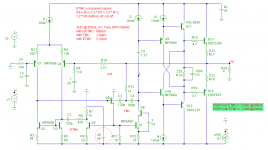
If applied to a complementary topology + CMCL, the additional cost (red stuff) is virtually nihil.
This is because the CMCL circuitry (blue stuff) contains already the copies of the VAS (Q13 & Q14).
Cheers,
E.
PS: The IPS is a CFB one, drawing 2mA at the outputs.
Hi Edmond,
Thanks for the explanation. Looks like a good circuit that is inexpensive to implement.
Cheers,
Bob
Hi Bob,
If applied to a complementary topology + CMCL, the additional cost (red stuff) is virtually nihil.
This is because the CMCL circuitry (blue stuff) contains already the copies of the VAS (Q13 & Q14).
Cheers,
E.
PS: The IPS is a CFB one, drawing 2mA at the outputs.
Attachments
Last edited:
Hi Jan,
Indeed, the amount of (positive) feedback provided by the 'E part' is critical. BTW, essentially just as critical as with any other error correction scheme.
There are many components involved that have a significant effect on the amount of EC: R3, R5, R9, R12, R13, C2, C3 & C4. Obviously, with that number of components, you will need precision parts and/or a trim pot (preferably in series with R7).
The value R8 is not that critical, as this one, together with R7 and C2, determines the HF roll-off (corner) frequency of the PFB loop, normally a few MHz. It serves the same purpose as the frequency compensation in Bob's HEC OPS (R34, R36, C6, etc)
Cheers,
E.
edit: Also notice the beneficial effect on the PSRR of the negative supply rail.
Thanks Edmond.
In my experience, since you can model any PS effects as an error component in the gain transfer function, an 'ideal' ec scheme would automagically lead to infinite PSRR. Which you are aware of.
jan didden
PSRR
Hi Jan,
I'm sorry, but in this case it simply doesn't apply. In a conventional 'blameless' amp, Cdom is referenced to one of the supply rails. Therefore, as we all know, the PSRR is rather moderate, in my example 33dB @ 10kHz
In the example of ETMC a few page back, one more cap with the same value is added (C2=C3), but tied to the other side of the current mirror. In this way the detrimental effect of Cdom on the PSRR is (more or less) canceled. For the same reason it's essential that the top of R7 is connected to ground.
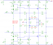
If referenced (via an appropriate voltage source V6) to the negative supply rail (see pic), the PSRR improvement is completely destroyed, i.e. back to 33dB from 58dB @ 10kHz.
This gives strong evidence that the improvement in PSRR does not rely on error correction, rather on balancing of the capacitive loads at both sides of the current mirror.
Notice that the other side of C3 is tied (via R12) to the output, so the other side of C2 (via R8 & R7) has to be tied to ground.
Cheers,
E.
Thanks Edmond.
In my experience, since you can model any PS effects as an error component in the gain transfer function, an 'ideal' ec scheme would automagically lead to infinite PSRR. Which you are aware of.
jan didden
Hi Jan,
I'm sorry, but in this case it simply doesn't apply. In a conventional 'blameless' amp, Cdom is referenced to one of the supply rails. Therefore, as we all know, the PSRR is rather moderate, in my example 33dB @ 10kHz
In the example of ETMC a few page back, one more cap with the same value is added (C2=C3), but tied to the other side of the current mirror. In this way the detrimental effect of Cdom on the PSRR is (more or less) canceled. For the same reason it's essential that the top of R7 is connected to ground.
If referenced (via an appropriate voltage source V6) to the negative supply rail (see pic), the PSRR improvement is completely destroyed, i.e. back to 33dB from 58dB @ 10kHz.
This gives strong evidence that the improvement in PSRR does not rely on error correction, rather on balancing of the capacitive loads at both sides of the current mirror.
Notice that the other side of C3 is tied (via R12) to the output, so the other side of C2 (via R8 & R7) has to be tied to ground.
Cheers,
E.
Attachments
Last edited:
1:5
I wrote "say 1:5". So 1:4 or 1:6 or even 1:10: will also do.
But 1:1 is far from optimal. Why? Read D.Self's article in Jan's 'bookzine'.
There is no reason why the capacitors should be in the ratio of 1:5.
All that is required is that they should be selected to give the desired unity gain frequency. In otherwords, select the capacitor values as you would for double pole compensation.
The resistor is then selected to give the zero necesary to cancel the pole in the minor loop's transmission before its unity gain crossing.
I wrote "say 1:5". So 1:4 or 1:6 or even 1:10: will also do.
But 1:1 is far from optimal. Why? Read D.Self's article in Jan's 'bookzine'.
Hi Jan,[snip]This gives strong evidence that the improvement in PSRR does not rely on error correction, rather on balancing of the capacitive loads at both sides of the current mirror.
Notice that the other side of C3 is tied (via R12) to the output, so the other side of C2 (via R8 & R7) has to be tied to ground.
Cheers,
E.
Hmmm. Yes I see what you mean but I don't quite grasp it yet.
I would think that a PS related disturbance on the Vas output would be 'corrected' just as any other 'error' in the Vas output (via de output voltage sensing). But the devil undoubtedly is in the details. I'll study it some more.
jan didden
- Home
- Amplifiers
- Solid State
- Bob Cordell Interview: Negative Feedback