 , I now realise the NP caps are on the DACs' supply rails and not directly in the analogue signal path.
Power supply
As others have noted a 9V ac power supply is enough to run the DACMagic. Maplin's 9V 3.2A AC adaptor (L53BR) seems to work well with the DACMagic, which sounds fine and runs slightly cooler.
The rectifier diodes in the +/-15V supply are S1D's (SM 1 amp). Like an earlier contributor I think replacing these with 6A or 3A diodes and replacing the four 1,000uF 50V filter capacitors may make an audible difference. The electrolytics after the 15V regulators are worth changing.
The six (2 pairs for balanced, 1 pair for unbalanced) non polarised electrolytic output caps are 470uF 16V. I have shorted them for now but am going to install Michicon ES and remove the shorts.
I can confirm that using XLR out via a XLR to RCA connector is a nice upgrade.
I bought this one: Neutrik adapter XLR female - RCA female NA2FPMF voordelig kopen | prijsvergelijking goedkoopste | XLR - RCA
It gives better dynamics and perhaps abit wider soundstage. Also bass seems more tonefull. I would say for 25 euros it is a good upgrade.
I bought this one: Neutrik adapter XLR female - RCA female NA2FPMF voordelig kopen | prijsvergelijking goedkoopste | XLR - RCA
It gives better dynamics and perhaps abit wider soundstage. Also bass seems more tonefull. I would say for 25 euros it is a good upgrade.
Hi, everyone.
So, I bought a second hand DacMagic from eBay with the purpose of getting some real life practice at hardware modding. Furthermore, it has 2 digital inputs (not counting USB), which is a perfect fit for my two PC's (media server+workstation).
Anyways, here are the mods I've done so far:
1. 470uF bipolar output caps replaced with Nichicon Muse ES of the same rating. This made the bass more defined and overall made it better, but not much improvement in the sound beyond that. Also replaced two 47uF caps in front of the DAC chips, but then I realized they weren't in the signal path. Not sure if it made any difference.
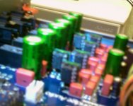
2. Six SOIC-8 opamps replaced with DIL sockets on browndogs; said sockets then populated with LME49720NA. This was the most effective mod so far, but also the hardest due to my lack of experience with SMD soldering. Difference from the stock DM is like day and night: soundstage is vastly improved, treble harshness is gone, vocal sibilance no longer feels like a spear piercing my eardrums. Attached is a picture of the mod (sorry for the quality, I took it on a 4-year old cell phone).
Didn't touch the analogue power supply yet. I assume replacing caps and regs there would yield further improvements.
P.S. My first post here, BTW.
So, I bought a second hand DacMagic from eBay with the purpose of getting some real life practice at hardware modding. Furthermore, it has 2 digital inputs (not counting USB), which is a perfect fit for my two PC's (media server+workstation).
Anyways, here are the mods I've done so far:
1. 470uF bipolar output caps replaced with Nichicon Muse ES of the same rating. This made the bass more defined and overall made it better, but not much improvement in the sound beyond that. Also replaced two 47uF caps in front of the DAC chips, but then I realized they weren't in the signal path. Not sure if it made any difference.
2. Six SOIC-8 opamps replaced with DIL sockets on browndogs; said sockets then populated with LME49720NA. This was the most effective mod so far, but also the hardest due to my lack of experience with SMD soldering. Difference from the stock DM is like day and night: soundstage is vastly improved, treble harshness is gone, vocal sibilance no longer feels like a spear piercing my eardrums. Attached is a picture of the mod (sorry for the quality, I took it on a 4-year old cell phone).
Didn't touch the analogue power supply yet. I assume replacing caps and regs there would yield further improvements.
P.S. My first post here, BTW.
Attachments
I can confirm that using XLR out via a XLR to RCA connector is a nice upgrade.
I bought this one: Neutrik adapter XLR female - RCA female NA2FPMF voordelig kopen | prijsvergelijking goedkoopste | XLR - RCA
It gives better dynamics and perhaps abit wider soundstage. Also bass seems more tonefull. I would say for 25 euros it is a good upgrade.
I have no idea why it would, just using an XLR cable with adapter does not do anything at all to the signal. but hey if it makes a difference to you, it makes a difference to you
It is said to bypass the two OP275's beside the 6 output caps. Anyway, I just ordered a pair of Burson opamps, which I'm going to put in that position and see if makes a difference on the RCA outputs.I have no idea why it would, just using an XLR cable with adapter does not do anything at all to the signal. but hey if it makes a difference to you, it makes a difference to you
ahh OK, thats a different angle to what I was understanding. well its really got nothing to do with the cable then, you could simply hook the internal XLR outputs up to the RCA sockets directly and use an RCA cable. this would still bypass the opamp and no special cable needed. even better would be to use a pair of line transformers from the balanced outs to the RCA, that way you get another 6db of DNR from folding down the whole balanced output signal
Does anyone have the service manual for the DacMagic? Fidelity Audio (former audioupgrades) seems to have removed it from their site due to copyright issues. I managed to download the 740C manual from Google cache, but I'd like to take a closer look at the power supply circuitry of the DacMagic. From what I gather it's using some sort of AC voltage doubler to feed the two +/- 15V regs.
Balanced or unbalanced
I can see your thinking there and the circuit uses a stereo DAC on each channel for SNR and distortion improvements. I suspect the colouration from the transformers would be more audible than the benefits of summing the XLR outputs to get an unbalanced output. The easy way is just using the output on pin 2 and grounding pin 1 (don't ground pin 3) of the XLR plug to get the signal to a phono plug.
Shorting or replacing the 470uF output caps makes a big difference to the sound in any of the above.
ahh OK, thats a different angle to what I was understanding. well its really got nothing to do with the cable then, you could simply hook the internal XLR outputs up to the RCA sockets directly and use an RCA cable. this would still bypass the opamp and no special cable needed. even better would be to use a pair of line transformers from the balanced outs to the RCA, that way you get another 6db of DNR from folding down the whole balanced output signal
I can see your thinking there and the circuit uses a stereo DAC on each channel for SNR and distortion improvements. I suspect the colouration from the transformers would be more audible than the benefits of summing the XLR outputs to get an unbalanced output. The easy way is just using the output on pin 2 and grounding pin 1 (don't ground pin 3) of the XLR plug to get the signal to a phono plug.
Shorting or replacing the 470uF output caps makes a big difference to the sound in any of the above.
It bypasses the opamps in the dac output stage. At least thats what its supposed to doI have no idea why it would, just using an XLR cable with adapter does not do anything at all to the signal. but hey if it makes a difference to you, it makes a difference to you
")
Back to the inside of the box...
The SO8 op amps (U55/56/59/60) are 5532's, I have changed them for 4562MA's in SO8. Early days yet but they sound fine a day in and will probably get better as they burn in. If you haven't changed SMD IC's before they are tiny and the PCB tracks are thin and fragile so be careful. The first IC was hard work and the PCB track repairs took ages, the second IC was much easier and the tracks just needed a quick wipe with the iron tip!
The other changes I am planning are swapping power supply capacitors:
- Panasonic FC's for the polarised caps in the analogue supply (2,200uF, 1,000uF, etc.)
- Rubycon ZA for the 10uF 35V digital supply decoupling caps
- I already have some Michicon Muse ES 470uF for the outputs but may just leave the bypass wires in.
I will post some notes later and try to draw my SMD extraction routine if anyone's interested?
Last edited:
I accidentally lifted two solder pads and melted some film caps when trying to desolder the opamp at U60. Somehow everything works fine, including the caps (though I'm going to replace them anyway; don't like the burned look). The Browndog I put in there seems to be held in place by the remaining pads.PCB tracks are thin and fragile so be careful.
Do it; might save someone from killing the PCB.I will post some notes later and try to draw my SMD extraction routine if anyone's interested?
Okay, now for the upgrade plans. I've noticed that Fidelity Audio is using polarized caps around the DAC chips in their upgrades:
An externally hosted image should be here but it was not working when we last tested it.
Makes sense, considering they are power supply decoupling caps. I'm going to replace them with Panasonic FC/FM when they arrive, same with the 10uF caps near the regulators. I'm also going to install TO220 sockets in place of the regs so that I can easily swap them without soldering.
Fatmangolf said:I will post some notes later and try to draw my SMD extraction routine if anyone's interested?
VIDEO
Here is that picture guide to lifting SMD pins
This is not to scale - SO8's are tiny, about the size of the letters on my PC keyboard! The black thing is some kind of thin hooked tool e.g. one of the Maplin soldering tool set N18AN, and you may find a magnifying lens helpful.
Hope this helps, please take great care and I accept no responsibility for the consequences!
Last edited:
Glad to mod
Like gtx580m I am going to try polarised caps on the digital decoupling, I have some Rubycon ZA's which I read were very good for this role. I am sure the FC or FM would be great as well. Agreeing with gtx580m I think Fidelity Audio use Oscon SEC's, which are polarised and low impedance I think.
Like gtx580m I am going to try polarised caps on the digital decoupling, I have some Rubycon ZA's which I read were very good for this role. I am sure the FC or FM would be great as well. Agreeing with gtx580m I think Fidelity Audio use Oscon SEC's, which are polarised and low impedance I think.
Last edited:
Interesting product
Good lead, I will take a look for next time I dare to do SMD.
Good lead, I will take a look for next time I dare to do SMD.- Home
- Source & Line
- Digital Line Level
- Opening the new DacMagic????