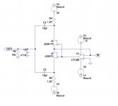
For those of you looking for the silver bullet to input impedance concerns, this is how it is implemented on my board - The amplifier is not in the audio path. It reduces the input impedance from 10-15 ohms to less than 1 miliOhm (~0.0005 ohms or so) as drawn!
I have included a picture of the original version that uses followers instead of an amplifier to accomplish the same thing if adding the amp takes away too much from the Zenness.
The amp version also brings the jfet offset inside the loop to keep input offset at essentially zero. Secondarily, putting the offset voltage you need into the + amp input is all you have to do for DACS like the 1543/5 and Sabre!
Adjust the voltage, resistors, and/or number of jfets as in the article and other posts for the DAC you have...

Dave
I have included a picture of the original version that uses followers instead of an amplifier to accomplish the same thing if adding the amp takes away too much from the Zenness.
The amp version also brings the jfet offset inside the loop to keep input offset at essentially zero. Secondarily, putting the offset voltage you need into the + amp input is all you have to do for DACS like the 1543/5 and Sabre!
Adjust the voltage, resistors, and/or number of jfets as in the article and other posts for the DAC you have...
Dave
Attachments
For those of you looking for the silver bullet to input impedance concerns, this is how it is implemented on my board - The amplifier is not in the audio path. It reduces the input impedance from 10-15 ohms to less than 1 miliOhm (~0.0005 ohms or so) as drawn!
I have included a picture of the original version that uses followers instead of an amplifier to accomplish the same thing if adding the amp takes away too much from the Zenness.
The amp version also brings the jfet offset inside the loop to keep input offset at essentially zero. Secondarily, putting the offset voltage you need into the + amp input is all you have to do for DACS like the 1543/5 and Sabre!
Adjust the voltage, resistors, and/or number of jfets as in the article and other posts for the DAC you have...
Dave
Bravo!
For those of you looking for the silver bullet to input impedance concerns, this is how it is implemented on my board - The amplifier is not in the audio path.
Can you explain how the opamp isn't in the signal path if it doesn't have a low pas (1hz) filter?
Thanks for sharing this "upgraded" ZEN I/V !
On which specifications did you decide to choose the LT1468?
What about the AD847.....
Piersma,
My pleasure. I chose the opamp for low input offset and drift, low input bias current, low input capacitance, and a reasonably wide bandwidth.
I have used the 1468/9 previously and also like it for other reasons. It is a very simple topology and has low distortion with low noise and a comparatively wide bandwidth.
I have no experience with the AD847. From the datasheet, it looks like it would probably work well. Try it and see.
Can you explain how the opamp isn't in the signal path if it doesn't have a low pas (1hz) filter?
The op amps contribution to the audio path is its input parasitic parameters. Specifically, the 1468 has about 4pf of input capacitance and 3nA of input bias current on the negative input. A 1Hz filter defeats the purpouse of the amp (or the discrete feedback).
The opamp turns the transimpedance amplifier (the Zen I/V) into a folded cascode transimpedance amp. A fet input amp should also be a good choice as long as you balance the input capacitance rise vs the imput bias current decrease from one of these. The offset will likely be a little worse as well, but nothing to worry about.
Aside from this, the decrease of input impedance to the I/V stage could also be considered as the opamp's contribution to the audio path - which should be a measureable reduction in the distortion of the current output from the DAC caused by the high input impedance of the stock I/V stage. This will be dependent on the DAC itself and the number of jfets in parallel.
I will have to defer any real world listening impressions until I have one built some weeks from now. As I said previously, I will be building them both ways to see what sounds the best to me with both a parallel 1543 and a Sabre. I will also try to do some measurements with and without so we can see what the real advantage to this addition is. I intend to stay away from 1 bit pwm DACs with this because of the need for a high order low pass filter at the output.
I look forward to comments from anyone on the Zen I/V once up and running!
Dave
Last edited:
> It's beautiful. Where to get/buy some?
Just follow that link and there are instructions how to contact Mark Lai.
Also see :
http://www.diyaudio.com/forums/soli...-high-performance-source-follower-module.html
if you want to add a buffer after the output IV resistor.
Patrick
Just follow that link and there are instructions how to contact Mark Lai.
Also see :
http://www.diyaudio.com/forums/soli...-high-performance-source-follower-module.html
if you want to add a buffer after the output IV resistor.
Patrick
Hi Ichi,Hi fitzfish,
referring to circuit in post#241, would it be possible to increase the value of resistors R6 & 10 from 10k to 100k so as to decrease the required 10uF value of capacitors C1,2,4,5 to 1uF? The reason being a less expensive high quality cap.
Ichi
Yes you could, although I would strongly suggest a follower or buffer of some sort after the load resistor - something like the one in the second picture of that post will work. B1 and other symmetrical follower buffers are in keeping with the Zenness of it. EUVL posted a link to a lower noise version a few posts up. There are a number of Zen types of gain stages as well that could be used, your choice here.
If you like the second circuit, I would move the (4.7nF in this case) low pass caps back inside the follower to prevent cable and load impedance changes from affecting the filter response. This is what I did on my board. Delete the 10K resistors and change the 10uF caps. The divider resistors for the feedback are the load.
The discrete version of the circuit will be set up comparitively loose and will not control the input impedance quite as well as the opamp version. A pot or adjusting resistor of some sort for the lower resistor in the divider would be a great idea. "Looser by necessity" here is to allow for thermal drift and other mismatches, but it will be interesting to see what it sounds like. I have a suspicion it might like it...
Dave
What is the voltage across the FET, and what is the current?
This is what i got Papa
- 2,31 Volt drop at 220R
- 17,19 Volt --> J74
17, 00 Volt --> K170
-Input DC Offset 3,7mV and 5,4mV
V supply +30,2 Volt and -30,0 Volt
Is this normal ?
Regards
La Ode
10 mA at 17 to 18 volts = 170 to 180 mW.
The devices are rated at 400 mW last time I looked.
I'm just little worried about those heat
So, this will be fine right
Thank you Papa
n.b.
this Zen I/V still playing with my PCM1704 till now.
i had try burn about 14 hours, and the heat remain constant.
Regards
La Ode
how do you compare Zen I/V with your previous I/V
My Previous I/V was D1
Well, i just want to say. THEY ARE BOTH GREAT
Thank's for wonderfull schematic PAPA
Hi Piersma,
I waffled a little bit about adding a discrete balanced to SE converter to it, but in the end decided to send it out as was. I have a 1543 parallel design complete that will fit in the cut out at the rear of the IV board and will use the Sabre config strictly for balanced operation once I get to that point. I want to compare old school R2R Dacs with a state of the art DAC.
I have the first quote back and am waiting on a quote from a second vendor and a re-quote in HASL (solder) as opposed to the more expensive gold I specified from the original vendor.
I am chomping at the bit to build it...
Dave
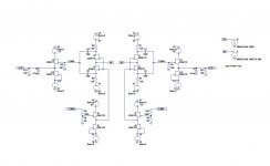
I am attaching a spice model of the output capacitor free dc coupled cascoded version. The models for the Mofsets aren't very good, obviously a trimmer will be needed to null the DC at the output.
The DC at the input is of more concern, if you use Mr. Pass's suggestion of a voltage divider to null the DC at the input we will affectively be inserting a passive I/V resistor, not sure this is a good idea, a CCS would be better I think, but it would have to handle a very low current?
The DC at the input is of more concern, if you use Mr. Pass's suggestion of a voltage divider to null the DC at the input we will affectively be inserting a passive I/V resistor, not sure this is a good idea, a CCS would be better I think, but it would have to handle a very low current?
Attachments
- Home
- Amplifiers
- Pass Labs
- Zen I/V Converter