...
I tried to measure signal at the input of the i/v stage. I could not detect any signal there.
anybody got a suggestion?
regards
joris
Do you have a oscilloscope, or really good AC voltmeter?
Simple DMM is not a right tool for this purpose...
Do you have a oscilloscope, or really good AC voltmeter?
Simple DMM is not a right tool for this purpose...
I'm using a scope.
I'm using a scope.
Burn 1kHz sinus signal as wav file on CD, play it through the DAC and you should be able to see the signal at 5mV/div setting on your scope.
Hi Juma,
That's sort of what i did but i used a 83Hz test signal. It's the only file i have at hand i can use. still searching for test signals. waveform, though not pretty, is the same as the standard tda1545 output so that checks out ok at the output.
Measuring at 20mv/division (sorry can't go lower), I can't see any signal at the input of the i/v stage. So for now it seems that any signal present must be below ~4mv. I set focus and intensity to the max so the lowest signal i can detect is about 2mv.
regards,
Joris
Jazz,
regardless of matching and offset discrepancies, you say that your Zen I/V sounds right.
I'd say that it works all right too, but since you can't see the slightest trace of signal at DAC's output leads me to believe that something may be wrong with your scope ?
If its lowest setting is 20mV/div it may mean that you have some cheap scope that one can't really rely on...
What about this as another way to skin the cat?
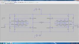
I left out the cascode (I was too lazy).
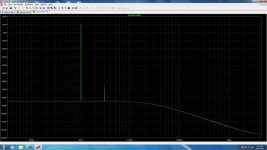
I added another gain stage to remove the large voltage drop seen on the power supply when parralleling the input devices.
Here is the basic circuit and fft of 4Vrms
I left out the cascode (I was too lazy).
I added another gain stage to remove the large voltage drop seen on the power supply when parralleling the input devices.
Here is the basic circuit and fft of 4Vrms
Attachments
Last edited:
progress
A couple of updates from me - My goal is to use jfets in the original configuration, maximize the performance by "sweet spotting" the input current, and minimize the input impedance by paralleling jfets and/or adding gate modulation.
I started down the 1541 path as well but have reconsidered. The Zen I/V really appears to like working at a higher current input because of the jfets comparatively low transconductance. Since I want to use an R2R DAC for this first attempt, paralleling DACs appears easy.
At least to me the 1541 is not as attractive to parallel because of the sheer size, the cost, and the complexity of the capacitor dividers. It is a bipolar supply part that does not require voltage offset to the gates, but I think that is not as much of an issue. Still need to test this...
The 1543 provides an easy way of paralleling 4-6 parts in a simple 8 pin package to get the current up in the optimal range. This is at the cost of higher noise and distortion. Still, it should be a good match for the Zen I/V performance. It also is simple enough that basic matching could be done by testing them one at a time. I suppose you could look for lowest distortion at this point as well from each converter if you had enough of them. The 1545 does improve on distortion and noise, but at 1mA p-p it would take many more in parallel to get where I want to go.
This still does not address the perception that input impedance will not be low enough with the I/V circuit for best performance, so I will use both more jfets in parallel and add the option for gate modulation.
The great news is that six 1543s in parallel produce about the same current as the Sabre in 4x4 stereo mode, so the circuit should work for either! The Sabre will require two more I/V converters as it is balanced.
Here is the basic DAC configuration I am suggesting -
Attachments
Last edited:
You get higher distortion with 2 gain stage (-80dB 3rd in balanced mode ?).
Patrick
Yes I agree.
This is not great performance.
Just trying to generate other ideas from people.
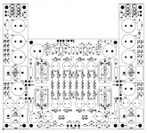
Here is the circuit layout. More time to point-to-point than just to lay it out, at least for me.
It uses simple mosfet follower power supplies with post regulators for the audio output voltage follower stage. It can handle one to four jfet pairs per channel, 2 channels included per board. It also has the zin compensation included that can be optionally populated, or not. The cutout at the top is a space for whatever DAC I want to use it with. It may look complicated but it is as simple as the original, paralled up a bit and mated with supplies. The Zin comp option is really the only added feature.
I probably went overboard with the supply capacitors, but I wanted it rock solid and quiet. I also included multiple population options for the DC block capacitors in the I/V stage and footprints for Dale type metal film and for vishay/caddock sized resistors. I do not know if I will test all of the permutations, but I figured I do not want to make the boards more than I have to if there is something I want to try...
Oh, and for the Sabre, the two power supply boards are scored and break away. I will add another I/V board on top (middle square part) and use one set of supplies for both.
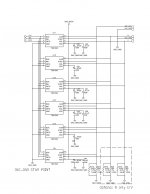
Schematic follows this with a zin comp option and all of the details and power supplies.
Layout is complete. Might be a month to get it up and working, don't know yet. As soon as I do, I will post details.

Dave
It uses simple mosfet follower power supplies with post regulators for the audio output voltage follower stage. It can handle one to four jfet pairs per channel, 2 channels included per board. It also has the zin compensation included that can be optionally populated, or not. The cutout at the top is a space for whatever DAC I want to use it with. It may look complicated but it is as simple as the original, paralled up a bit and mated with supplies. The Zin comp option is really the only added feature.
I probably went overboard with the supply capacitors, but I wanted it rock solid and quiet. I also included multiple population options for the DC block capacitors in the I/V stage and footprints for Dale type metal film and for vishay/caddock sized resistors. I do not know if I will test all of the permutations, but I figured I do not want to make the boards more than I have to if there is something I want to try...
Oh, and for the Sabre, the two power supply boards are scored and break away. I will add another I/V board on top (middle square part) and use one set of supplies for both.
Schematic follows this with a zin comp option and all of the details and power supplies.
Layout is complete. Might be a month to get it up and working, don't know yet. As soon as I do, I will post details.
Dave
Attachments
interesting, but do people really feel that caps are a better solution than a servo? I see so many designs that at least for my taste would be so much better without coupling caps, as for me that is one of the major benefits of going balanced in the first place.
also would it not be better to allow some way of thermally coupling the jfets together by putting the patterns back to back rather than side by side?
also would it not be better to allow some way of thermally coupling the jfets together by putting the patterns back to back rather than side by side?
Hello qusp,
The coupling caps in the I/V portion of the original circuit are absolutely necessary, at least as far as I can tell. The drain voltage for the k170 is at around +15V in the original circuit. The drain for the j74 is at about -15V. Simply shorting these two points together would kill it functionally.
You could take these two points and feed them into a wide range common mode input opamp of some sort and do away with the caps, but my opinion is that this would add to much complexity in the sound path vs. the caps themselves.
I did not use coupling caps anywhere else through the follower stage to the output after the I/V. The follower is there to isolate the low pass filter and provide for cable drive in my case. It can be easily left out when assembled.
I gave putting them face to face some thought. In the end, it routed better when set up to use euvl's little heatsinks. I may also try a block that covers all four sets in a channel. Just have to see once there.
Regards,
Dave
yeah like I said, a matter of taste for servo or cap, I prefer servo personally, but cap is fine also. I didnt realize you were using EUVL's TO92 sinks, nice one, well that should work out just dandy then. they look pretty sweet too  i'll keep an eye on your progress. i'm kinda collecting IV stages at the moment, looking forward to ackos JFET version for sabre as well.
i'll keep an eye on your progress. i'm kinda collecting IV stages at the moment, looking forward to ackos JFET version for sabre as well.qusp,
I am in the same boat, although just starting out. I am looking for an I/V stage for the Sabre that fits my tastes. I'll keep you posted.
Patrick,
Not really sure yet. I eyeballed it for the original placement and am waiting on the ones I just ordered to come in before I send out the artwork. I did not find a mechanical drawing anywhere for it, but could use one to speed up the process. I'll PM you with my email.
Thanks,
Dave
- Home
- Amplifiers
- Pass Labs
- Zen I/V Converter