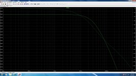
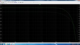
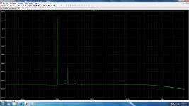
P.S. I think OS had some Cmult in one of his amps, maybe he can say how they behaved when the amp was fully driven. He must have been seen some loss after the multipliers too if fed off the main Tx too. Also can his THD % and spectral differences with BJT subs be affected by different accuracy between companies models up to a point?
As far as the regs go, I think either the 4793/1837 or the 669/649 will work well for the slave, and the master can be 2N5551/5401. How do we like these choices?
Are there better high voltage transistors than the 2N5551/5401? These are very tempting since they're so cheap from Profusion. 100 for $3. Enough for rapid, destructive prototyping!
Or perhaps someone knows of a good 5W type? The frontend draws very little current, and 33mA at 110V is 3.6W. Enough margin for error? During normal listening, Vce will be no more than 5V, so the tough part is when powering up, since the CCS will engage at a low voltage and instantly ramp up the frontend to its max mA. If not for this, we might be able to use the 5551/5401 for both the master and slave.
- keantoken
Hi,Regulator vs. C-multiplier
Don't ask me! Andrew, what's the difference?
The bass improves with the NPN version because the transistors use have higher gain, as is almost always true for NPN devices over PNP.
The design was to stretch the limits of the traditional C-multiplier. A design can only be as good as the parts that make it. This means if we extract the best performance out of two circuits using different parts, there MUST be differences.
the Cap Multiplier attached to this post has a pair of resistors feeding a fixed proportion of the Vcc to the base of the Mult output transistor.
When near zero current is drawn through the output, the input voltage is Vcc0, i.e. the unloaded supply rail voltage.
The voltage at the base and it's capacitor is a fixed proportion of this. Just for this example let's take 1k0 and 9k0 (It's not a preferred value). The output voltage of the multiplier is Vcc * 0.9 - Vbe0.
If only a few mA are drawn the Vbe will be near 600mV. This Vbe does not change significantly if the range of output currents were say 10mA to 100mA.
The cap voltage will vary with base current drawn from it and with the charge fed back in through the 1k0. For low currents and for short transient currents approaching that maximum, the cap voltage will hardly change.
Essentially we have Vout ~ [Vcc0 * fixed ratio] - Vbe.
That is the way the multiplier works. One sizes the component values to achieve acceptable output ripple for the range of operating conditions one expects. The Capacitor * hFE is the multiplier effect. It does not store energy. It slows down the reaction to current demand by a factor directly related to hFE.
Now, we modify the Multiplier and replace the 9k0 with a Zener. This is virtually equivalent to Zener Follower Regulation. Pass and many others use them.
The output voltage is VZener - Vbe. Note that input voltage (VccA) has only secondary effect on output voltage.
Now we move to the schematic posted by Salas.
Replace the 9k0 with an open circuit.
The capacitor/base voltage is ~ VccA - Vr1k0.
The circuit output voltage is ~ VccA -Vr1k0 - Vbe.
VccA is the actual rail voltage that is varying with the demands on the main supply.
V1k0 varies with the output current/hFE.
Vbe varies, as in the multiplier, as load varies from 10mA to 100mA.
I can see that this circuit without the 9k does not achieve the same as the Multiplier and it also cannot perform as a Zener Follower.
It is a sort of corrupted regulator. It is certainly not a multiplier. Adding a pair of diodes does not bring back the multiplier action, although it does move it closer, if the components are chosen to keep the ripple on the capacitor similar to that in the Multiplier.
Remember that Zener.
If we add a Zener in series with the 9k0 we can still get multiplier action but as Vcc rises to Vcc0 plus the tolerance of the mains supply voltage, the Zener puts a knee in the curve Vout vs Vinput. It starts to reduce the slope of the fixed ratio to something less. It helps prevent the voltage amplifier stage from going overvoltage when the worst case operating conditions are stacking up against the devices one has chosen.
Thanks for confirming that the NPN Mult output transistor allows the -ve version to perform better. But it does not explain why the performance is worse at the extremes of the frequency range.
Last edited:
keantoken,
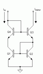
This is how I implemented it in one of my folded cascode designs.
Notice the trimpot for offset adjustment........just an idea.
Another way is to attach a trimpot across one of the mirror's emitter resistor, the side that does not have the bias circuit.
Regards,
Jam
This is how I implemented it in one of my folded cascode designs.
Notice the trimpot for offset adjustment........just an idea.
Another way is to attach a trimpot across one of the mirror's emitter resistor, the side that does not have the bias circuit.
Regards,
Jam
Attachments
Last edited:
This is how I implemented it in one of my folded cascode designs.
Just wondering... how can some of you designers come up with such a decision to put IRFP240/9240 in that position (driving the output BJT)???
Well of course, you don't have to always design a "best" amplifier.
how can some of you designers come up with such a decision to put IRFP240/9240 in that position (driving the output BJT)???
Nelson Pass - Threshold Stasis series
Dieter Burmester - 828 Model
John Curl - Halo JC-1
Hi Jay,
That was just a prototype and those devices were handy, The final version used Toshiba mosfets as drivers and yes you have to bias mosfet drivers harder than bipolars to get them into their linear region.
The board design allowed me to remove the drivers and output bipolars and replace them with an all mosfet output stage.
But step back for a moment and look at the advantage of mosfets as drivers
a) No need for triples - one less pole to deal with
b) Easier to drive
c) Less loading on the vas
d) No beta collapse
e) .......and so on (does I like them count?)
This is not to say you can't do a good job with bipolars but mosfets can be useful in the VAS and driver stage.
Today I would never use mosfet's as input devices if I can help it, but this is a fairly old design. I think jfets are the way to go.
Regards,
Jam
Last edited:
Thanks jacco - you rule!
Thanks Jam, for the explanation. At least I know you ended up with something else.
Jacco, Nelson Pass seems to have unique objectives in his designs. And even in his own amplifiers the Stasis is hardly the best.
John Curl is someone else. But I'm not sure that he uses IRFP240/9240.
There are things that you have to have, to compensate for the use of such device imo:
(1) You have to have the mosfet running in class-A
(2) You want to have a relatively high power amp.
(3) You need to have an "expensive" dedicated power supply for the mosfet
(4) I don't know about Krell KSA slew rate, but I think I would prefer KSA.
BTW, treble sound quality might be highly compromised with the mosfet. I haven't heard non of the above amps. Only similar design by Boraomega (DOGC MkIII), which uses IRF530/9530.
- Home
- Amplifiers
- Solid State
- Goldmund Mods, Improvements, Stability


