I can't find see the grid current data you're referring to, maybe I'm being stupid. (Or did you mean the reverse current data, which implies that the E83CC is actually better than the E88CC, considering it is operating with about 1/10th the bias, and has tighter tolerance too...)
Last edited:
(Or did you mean the reverse current data, which implies that the E83CC is actually better than the E88CC, considering it is operating with about 1/10th the bias, and has tighter tolerance too...)
No MerlinB, column II sets the standard for a good valve. The 88 is better (or the same if you compare them after some intensive use) in terms of reverse grid current both on paper and in practice in my experience.
Column III just means end of life which, for good stuff, comes after at least 15000 hours of "proper" use.....
45
Hello,
This discussion of triode noise is interesting. Assuming that we employ low noise circuits like a cascode to maintain the high gm of the tube is there fruit in the results? Or is this just an academic discussion? Has anyone done a FFT and graphed the noise performance?
I am now building the Salas JFET RIAA preamplifier. Will an optimized triode RIAA preamplifier be in the same class as far as noise?
DT
All Just for fun!
Hello,
This discussion of triode noise is interesting. Assuming that we employ low noise circuits like a cascode to maintain the high gm of the tube is there fruit in the results? Or is this just an academic discussion? Has anyone done a FFT and graphed the noise performance?
I am now building the Salas JFET RIAA preamplifier. Will an optimized triode RIAA preamplifier be in the same class as far as noise?
DT
All Just for fun!
In my experience solid state is better in this department.
However more than the noise itself, in terms of dB's, one should evaluate first if noise modifies the signal or not.
If that kind of noise does not correlate to the signal (i.e. there is just a superposition without altering information carried by the signal) your brain will bypass it easily and quickly! This is also why vynil just works better!!

45
In my experience comparing the subjective results from various valve and Jfet, op-amp, BJT, phono I have made, although when covering the vinyl's SNR it will not obviously add noise when actually playing, the lower noise floor circuits pass more detail still. Could understand that also by comparing perfectly adequate regs with even quieter and more dynamic ones. Especially under 300Hz where the Riaa gain is high and the corner noise frequency of elements progressively worsens their noise curves, some readable noise floor lowering on the FFT comes across like easier to follow bass lines, beats, and male voices. A doubled up JFET 58dB (DT makes 43dB, less noise gain) shows -107dB @ 20Hz for -10dB 1kHz signal ref 0dB 1VRMS from a 15R 0.3mV source. At 20kHz it hits the particular FFT's limit at under -140dB noise floor due to the Riaa shape and better en higher up. You got to see some same conditions full sonic BW FFTs from best tube stages for noise to have an answer to the original question of how they compare. SY's is one of the best, I would recommend it as tube alternative, and it will be nice to see, if he will be kind to provide a full spectrum chart at 300mV 1kHz out Ref 1VRMS 0dB with good visual octave spread in the lows. An input transformer actually holds a benefit for both low en tubes and Fets since it shows them a higher Zo that they feel better with for noise lower in the spectrum. Alas, the secondary's resistance adds Rn, back to near square 1 at 1kHz & up, but the total noise floor curve is evener across the sonic spectrum. The 58dB double Jfet chart in is the green on black. Source 15R atn cable on input, I.e. almost grounded. Cable lends -90dB hum pick up. Totally open flapping about input is next green chart.
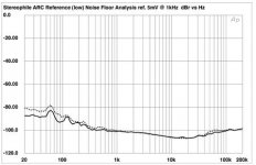
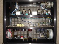
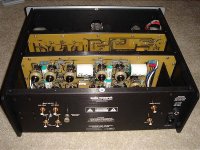
P.S. I found this on Stereophile for AR Ref phono ''While many designs (including AR's PH3 and PH3 SE models) use solid-state-based "head amps" to boost the ultra-low voltages produced by some moving-coil phono cartridges, the Reference uses a pair of premium Jensen transformers to give the High Gain input an impressive 69dB of gain (63dB is available as a factory-installed option) with ultra-low noise specs—and no transistors in the signal path. The Low Gain input, which bypasses the transformers, gives 48dB of gain (43dB is available as a factory-installed option). Both inputs are compatible with moving-coils, and while AR gives you a guide as to which input to use with an MC cartridge of given output, some models will fall in between, in which case use the input that sounds best.
"Eleven dual-triode 6922 (6DJ8) tubes handle the amplification. Passive HF equalization is applied to the first group of tubes, while the LF boost is achieved through an active feedback circuit.''
And its noise floor measurement, to get a picture for DT's question in general. Referenced 5mV input at 51dB measured gain (low setting). There is probably some triode paralleling going on in the head amp hinting by the number of tubes used BTW.
I am now building the Salas JFET RIAA preamplifier. Will an optimized triode RIAA preamplifier be in the same class as far as noise?
DT
All Just for fun!
P.S. I found this on Stereophile for AR Ref phono ''While many designs (including AR's PH3 and PH3 SE models) use solid-state-based "head amps" to boost the ultra-low voltages produced by some moving-coil phono cartridges, the Reference uses a pair of premium Jensen transformers to give the High Gain input an impressive 69dB of gain (63dB is available as a factory-installed option) with ultra-low noise specs—and no transistors in the signal path. The Low Gain input, which bypasses the transformers, gives 48dB of gain (43dB is available as a factory-installed option). Both inputs are compatible with moving-coils, and while AR gives you a guide as to which input to use with an MC cartridge of given output, some models will fall in between, in which case use the input that sounds best.
"Eleven dual-triode 6922 (6DJ8) tubes handle the amplification. Passive HF equalization is applied to the first group of tubes, while the LF boost is achieved through an active feedback circuit.''
And its noise floor measurement, to get a picture for DT's question in general. Referenced 5mV input at 51dB measured gain (low setting). There is probably some triode paralleling going on in the head amp hinting by the number of tubes used BTW.
Attachments
I was looking at column II. E88CC = 0.1uA, E83CC = 0.2uA. Not much difference, until you realise that the 88 is operating around -10V biasNo MerlinB, column II sets the standard for a good valve. The 88 is better
which suddenly makes it look rather pathetic!A cascode is only low noise when compared with a pentode. The cascode has similar noise to a normal common-cathode triode stage. The main advantage of a cascode is high gain, but this does not help the noise performance as the noise is boosted as much as the signal.low noise circuits like a cascode
I was looking at column II. E88CC = 0.1uA, E83CC = 0.2uA. Not much difference, until you realise that the 88 is operating around -10V bias
That's not pathetic because once you are in the regime of "ideal" negative bias the reverse current doesn't change too much. What I mean is that value is indicative for most of the usable I-V plane except when you approach 0V bias. Otherwise grid-leak bias wouldn't work so well.
However, with real valves in hand today (including those NOS), the situation is not as good as the data-sheet says....
45
Why is -10V bias for 0.1uA "pathetic"? The ionic current does not vary much with voltage, as the negative grid attracting more positive ions is offset by the reduced anode current creating fewer ions.
If we assume that 0.1uA is a typical grid current for a healthy valve then we are talking about 8.5nV/root Hz for a 50K source impedance. This compares with 28nV/root Hz for thermal noise from 50K. These together could be the dominant noise at higher audio frequencies. At mid frequency the impedance is lower so shot noise may dominate. LF is flicker noise.
If the input valve is biased insufficiently negatively then there will be more grid current so more noise. It might just be possible that HF signals from the cartridge would change the current enough to cause noise modulation, but I would expect this to be small.
The rising source impedance due to Riaa shape and its interaction with Ig must be the reason we can see the noise floor picking up as we go towards the highs in some valve phono stages, when the anti-Riaa naturally should have showing it going further down, maybe has to do with what we see in the ARC's noise floor as in its review chart also. Then again a Teflon input cap could help on that respect?
I was looking at column II. E88CC = 0.1uA, E83CC = 0.2uA. Not much difference, until you realise that the 88 is operating around -10V bias
That's with 15mA ip and 90V on the plate. The bias is actually closer to -1V if you read the spec sheet (grid supply voltage of +9V).
Hello,
Salas thank you for your post including attachments. I will take it as a yes that valves can have respectable noise performance. Also thank you for reinforcing the importance of the power supply in the amplifier.
DF96 I am not convinced that a common cathode stage versus a cascode stage is a coin toss in the realm of noise performance (speaking theory). Given the same valve in circuit the cascode has higher gm. Could be using an RF valve in an audio circuit everything is low frequency with flicker noise (1/f) increasing in importance?
Looking at the FFT’s valve Riaa noise can be black as my photo dark room. Dark enough not to fog the Ilford film.
DT
All just for fun!
No, given the same valve and bias a cascode has exactly the same gm as common-cathode. The difference in gain comes from the different output arrangements. The cascode largely isolates the lower valve from anode feedback, so the effective mu is raised to pentode-like figures. The raw signal current and noise current generated by the lower triode are the same as for common-cathode, but there is no anode feedback to then reduce them. The signal-noise ratio stays the same, except for a little extra noise from the upper triode - usually negligible.
I can't be bothered to look it up, but my gut feeling is that flicker noise in a typical valve starts below a few kHz? I think this is similar to a BJT or JFET? MOSFETs tend to start at tens of kHz, so can be more noisy for audio? GaAsFETs start flicker noise at tens of MHz, which is why they don't make good HF preamps but good from UHF to microwave. This illustrates the general rule that a good technology at one frequency is not necessarily better at lower frequencies. For audio purposes flicker noise has to be considered.
Carefully used, valves can have good noise performance. They can be beaten by well designed SS. For MM cartridges valves are good enough. For MC you need a transformer or SS.
When we're talking of input noise, the measurements and graphs presented earlier in this thread, don't state:
1) If is a shorted input,
2) 600 Ohm resistor
3) A "typical" MM-PU, with its inductance, resistance and its capacitive loading on the 47KOhm input terminals.
This is most important and should be mentioned. There will be quite different noise graphs.
When I measured RIAA input noise in the old days, we always used an real PU, monted in a my-metal box (this was a must due to many magnetic hum stray fields in the lab), to get the IRL readings. Nobody can play music with shorted inputs!!
Again I refer to the National Semiconductor papers I attached earlier in this thread, to see what a changing source (and noise) impedanse a real PU or MC transformer represents.
This also explains why the noise in the treble is not lowered according to the RIAA network. The termal noise from the PU rises on pair with the rising impedance and causes higher termal Johnson noise at higher frequencies.
Yes, the MM inductance will react with the shunt capacitance (from the cable etc.) to give an impedance which rises up at the HF end faster than the RIAA falls. This boosts both thermal noise and grid current shot noise. The basic noise is white, but it gets boosted at HF.
Yes.No, given the same valve and bias a cascode has exactly the same gm as common-cathode. The difference in gain comes from the different output arrangements. The cascode largely isolates the lower valve from anode feedback, so the effective mu is raised to pentode-like figures. The raw signal current and noise current generated by the lower triode are the same as for common-cathode, but there is no anode feedback to then reduce them. The signal-noise ratio stays the same, except for a little extra noise from the upper triode - usually negligible.
.
You should take the time to look it up. Lanford Smith, Radiation Designer's Handbook see section 12.9, Cascode amplifiers. The Cascode amplifier preserves the gm of the of the valve. The gm of the amplifier is equal to the gm of the valve.
You can not say that for a common cathode amplifier.
Just pieces of the puzzel. Lower noise? Worth testing.
DT
All just for Fun!
I had no need to look it up. Both cascode and common-cathode preserve the gm of the valve, and hence its noise behaviour. Apart from a minor correction: Langford-Smith shows that the gm is slightly lower in cascode (the opposite of what you are saying!).
There are two ways to analyse the common-cathode amp. One way treats it as a voltage amplifier with a finite output impedance, the other treats it as a transconductance amplifier with a shunting impedance. The latter is the one which uses gm. Valve gm is not reduced, but the gain is reduced by feedback from the anode; equivalently, signal current is shunted away by the anode impedance. If you want to reduce gm in a common-cathode amp then you have to add an unbypassed cathode resistor. You measure gm of any amplifier by measuring the current in an output short-circuit; you can then measure output impedance by seeing how this changes with different loads - I think you are confusing the two.
There is no "puzzel".
I can not understand all this talk of using the cascode for LF.
1) The lower tube sees a vertikal load line with higher distorsion as the result, and the upper tube gives a very high output impedance.
2) The output signal taken from the anode of the upper tube, will be refered to the B+powerline instead of signal ground or the cathode of the lower tube.
3) Power supply rejection will be down to zero.
So all power line noise and hum will be added to the signal when you take it out refered to signal ground!!
What have you gained?? Only to got rid of the miller capacitance Cga in the lower tube and shielding the output tube anode by the grounded grid in the upper tube. This results in very high and for audio unusable bandwith.....
All this was very good and a break-through for TV and FM radio input stages, but should IMO not be used in (HiEnd)-audio.
If you need higher voltage gain in an audio stage, use a penthode instead.
JohanB
I accept your criticisms of the cascode, but MM signals are small enough that the distortion is not a problem. PSRR is the real killer for audio cascodes. A pentode has exactly the same problems, plus partition noise too. If I wanted a stage with these characteristics, I would normally prefer a cascode to a pentode.
Radiotron Designer’s Handbook 4th edition page 534 formula (6).I had no need to look it up. Both cascode and common-cathode preserve the gm of the valve, and hence its noise behaviour. Apart from a minor correction: Langford-Smith shows that the gm is slightly lower in cascode (the opposite of what you are saying!).
There are two ways to analyse the common-cathode amp. One way treats it as a voltage amplifier with a finite output impedance, the other treats it as a transconductance amplifier with a shunting impedance. The latter is the one which uses gm. Valve gm is not reduced, but the gain is reduced by feedback from the anode; equivalently, signal current is shunted away by the anode impedance. If you want to reduce gm in a common-cathode amp then you have to add an unbypassed cathode resistor. You measure gm of any amplifier by measuring the current in an output short-circuit; you can then measure output impedance by seeing how this changes with different loads - I think you are confusing the two.
There is no "puzzel".
gm’ =gm gm’ is the amplifier, gm is the valve.
Look this part up.
gm = mu/rp this is gm for the valve, rp is the plate resistance.
gm = mu/(rp+R) this the gm of a common cathode amplifier. R is the plate resistor.
Toss in an unbypassed cathode resistor there is additional series resistance and the gm is reduced an additional amount.
The puzzle is this. Does it make any difference when the needle touches the vinyl? Perhaps a more inside the envelope look at the puzzle. Even in the text where 2.5/gm was printed, 2.5/gm was a generalization and the results among tubes would vary from the theory. Experimentation was recommended.
DT
All just for fun!
- Status
- This old topic is closed. If you want to reopen this topic, contact a moderator using the "Report Post" button.
- Home
- Amplifiers
- Tubes / Valves
- 12AU7 Phono Stage