I sort of agree, except that there can be a significant variation due to component tolerances anyway. It seems odd to put that much effort into making sure the bias doesn't drift with temperature, if you don't know whether it was right to start with.Second, it looks to my like this CCS was designed for low tempco, and this is smart considering the FETs use just a resistor for setting the bias right.
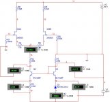
Something that keep's bugging me about this circuit is that there's no way to adjust the bias. I'm not familiar with these kind of output devices but the datasheet does indicate that the "turn-on" voltage can vary over a wide range. Is that not important?
I'm wondering if Goldmund doesn't have a way of setting the bias that's not shown on the schematic. e.g. R23 is shown as 330R, but maybe that's just a "typical" value, rather than cast in stone.
Scratch that, a temperature analysis would be useless since the FETs are located away from the CCS. There's no way we can expect the CCS to compensate the the FETs unless they are mechanically coupled.
With this, my opinion is that the "emitter-down" version is best, because of the lowest tempco and higher output impedance. As far as noise, we may never be able to tell.
- keantoken
With this, my opinion is that the "emitter-down" version is best, because of the lowest tempco and higher output impedance. As far as noise, we may never be able to tell.
- keantoken
Godfrey, that is curious. How can they get consistent sound without some method of setting bias? Nagys, is it possible certain components are tested and adjust in the factory, IE, perhaps for instance, R20 is adjusted at the factory to set the bias level?
- keantoken
- keantoken
Last edited:
I was wondering about that too. Maybe it just never got noticed. Doug Self mentioned in another thread that he once accidentally added an unnecessary (but harmless) resistor in a circuit. The cloners promptly started churning out exact copies of his amp - including the "mistake" resistor.It is also possible that Goldmund made a "benign mistake" perhaps...

I'm not sure how far to trust simulators wrt upside down transistors. Is there not some simple test you could do on an actual device to check real-world behavior....I will simulate tempco of the Goldmund amp using all 3 CCS types.
Sorry, my bad - it's R20 not R23.... perhaps for instance, R20 is adjusted at the factory to set the bias level?
They could well be avoiding trimmers for reliability reasons (this is expensive stuff, remember - it's not supposed to break).
They might use one in the factory though, to set the bias, and then replace it with a fixed resistor of the same value.
Shall I stir the pot a little more by wondering if there's any component selection involved in the input stage. (I believe jfet characteristics can be quite variable too.....)
Where's a "whistling innocently" smiley when you need one?
BTW, can someone tell me a little bit about the "fast" sound? I heard a sound I would describe as "fast" from my headphone amp, but I later discovered this was because of HF distortion coming from being overcompensated, which causes HF distortion when the frontend sees a capacitive load. I got the compensation to the right value, and the soundstage opened up, and a lot of harshness was eliminated. Thing is, my headphone amp is VERY fast. Gain-bandwidth product is 13MHz. This situation theoretically is not much different than in such an FET amp, where the FET capacitance effects the frontend. Anyone else have experience here?
- keantoken
- keantoken
I don't understand the 31.7kHz in the margin.Just for people who have not been acquainted with F5, here is the frequency response.
Should it read 3.17MHz?
Wait, your right MJF, I got that backwards. I was simulating with the other transistor flipped.
All my CCS simulations officially DON'T COUNT.
Okay, let's start again... Having the right transistor flipped, the only things to be affected should be noise and tempco.
- keantoken
All my CCS simulations officially DON'T COUNT.
Okay, let's start again... Having the right transistor flipped, the only things to be affected should be noise and tempco.
- keantoken
Stepping back for just a second or two...
It is truly fascinating to see over the course of a few days the tremendous talent, intelligence, ingenuity and somewhat friendly give and take over what constitutes the "correct" topology of the constant current source in a circuit.
This forum, and the internet have in its own way brought together men and women from truly around the world to share and help each other learn. Having been involved in electronics for a "few" years it is amazing in more ways than one. So lets get back to the task.
Carry on LADIES and GENTLEMEN... THANKS
Out of curiosity, what is the copyright/IP situation with publishing these schematics on the site? I recognize that people aren't discussing the amps for purposes of resale, but I'm wondering if we're not skirting the law by posting reproductions of the original schematics.
Hi Alex,
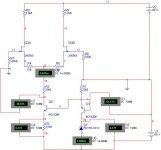
In Post#549 the pcb matches the schematic which does not match the schematic in Post#490. But the one in Post#490 does match that of the hand-drawn schematic in Post#1. So...... I am getting confused.
Other guys:
quote for PCB
new size : 205x88mm
Single side : $14 / pair
Double side : $22 / pair
I am ready. I still need the files from Alex (well, the final ones), and Alex, that won't be a problem right? . If we go for double side pcb for the main board then the daughter board will have to be made by another order.
Your can send email to tony_chan_cf@email.com, stating your forum ID, email address (which I will not post on the status report) and quantity (in pair). I will post the status report every day.
D2, D5, D4, D3, and T6 are all incorrectly connected. I know this amp and this circuit and I can promise all potential builders that it will not perform correctly. Beware.
The diodes can be reversed/changed while building the amp, no big deal. No changes are necessary to the PCB.
However, T6 cannot be easily rotated on the existing PCB. The PCB's tracks would have to be modified around T6.
EDIT: Actually, T6 can be rotated 180 degrees and its legs can be manipulated to make it still work. Kind of silly, but it would still work correctly. I'll still do the group buy. Anyone who connects the diodes and T6 the way it's shown in this schematic, please do not come to me for help. To make your amplifier operational.
THIS is the reason I suggested everyone "slow down". A good precise DIY project will at least take a couple weeks to double check , even triple check. Without drafting software, I still have yet to have a lead spacing or electrical error. This is not as easy as some may think.
OS
Last edited:
Out of curiosity, what is the copyright/IP situation with publishing these schematics on the site? I recognize that people aren't discussing the amps for purposes of resale, but I'm wondering if we're not skirting the law by posting reproductions of the original schematics.
My thought exactly , with just a slight change to , the CCS , for example .. IP considerations would be solved. Goldmund might not be too happy with it's present form. Would be the same as presenting a "NASKA" for DIY purposes.
I clone things , but always incorporate just enough change to "make it mine".
Just something to consider.
OS
I don't understand the 31.7kHz in the margin.
Should it read 3.17MHz?
That value moves with the position of the cursor on the screen, so you can point at an area of interest and measure the x and y coordinates.
It has nothing to do with -3dB point.
- Home
- Amplifiers
- Solid State
- The Very Best Amplifier I Have Ever Heard!!!!