Here you make two mistakes. There is no problem with the high freqs with wavelets. And the phase reference is defined by the impulse response and the wavelet do not change it.
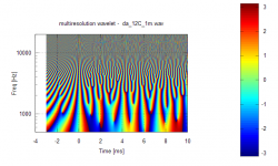
Here I attach a plot of wavelet phase of a loudspeaker. The phase plot is in the reange [-pi...pi]. You can have the phase at every given frequency at the every given time you like.
If the impulse response would be ideal the phase at t=0 is zero at every frequency. This loudspeaker comes quite close but it is not ideal.
- Elias
Wavelets are by no means the optimal TFR, the wavelet transform distorts amplitudes (HF is attenuated) and does not maintain absolute phase reference.
Referenced to an absolute time, as an example the phase values in a Fourier Transform are referenced to t=0
Attachments
Elias, you haven't understood either statement, but nothing new there. I can't be bothered to explain it to you, given the poor results that has produced in the past. Read through Stockwell's papers "Why use the S-transform" and "A basis for efficient representation of the S-transform" for a detailed explanation, you can find them here.Here you make two mistakes. There is no problem with the high freqs with wavelets. And the phase reference is defined by the impulse response and the wavelet do not change it.
I am wondering what we can do with the S transform here. Sure, it's used consistently in control system analysis before the controll system is implemented in digital form. Even in such cases, nonlinear modeling is often required to model the Device Under Control. While it's possible to do an S transform with data in audio, why would we want to do it and how will it fit into the audio design process?
Hi Michael,
Maybe can repeat the simulation but first set the low pass corner freq below 20Hz (the green curve below) to equalise the dipole in the pass band.
Here we go
")

Below are plots of a CMP system (OB or whatever you want) with the same 1ms delay time as is in all my simus done in my paper (and above FR plot / green and blue traces).
I show how amplitude develops along time line (transient response) for sine bursts of 6ms duration at frequencies of 125Hz 250Hz 500Hz 750Hz 1000Hz.
To make clear how a perfect CMP correction (like outlined in my paper) would work compared a simple 6dB correction (like usually used to correct for FR slope towards low freqeuncies in OB) I have set up the full equivalent circuits.
The traces for the 6dB LP at 20 Hz filter are amplified by 20dB to match level.
The traces for ideal CMP correction are amlified ligktly below 1 to make them dstingusihabel from input signal.
The input signal is LP filtered by 12dB / octave with a -3dB corner point around 250 Hz (as seen in my FR Plot above)
Below 1000Hz sine burst of 6ms duration

Below 750Hz sine burst of 6ms duration

Below 500Hz sine burst of 6ms duration

Below 250Hz sine burst of 6ms duration

Below 125Hz sine burst of 6ms duration

Maybe “acceptably” (sometimes funny) traces with the -6dB @ 20Hz push up correction – yeah – but not exactly a 100% CMP correction for OB speakers, I'd say.
Please look at this picture:
An externally hosted image should be here but it was not working when we last tested it.
…
Would you honestly say that you can not make an evaluation of which of these would be acceptable for a loudspeaker?
...
All your arguments are just running in circles.
John, its hard to believe that this comes from you.
I mean – you are the man around here that is the most dedicated to - and skilled in - technical perfection (which by no means is to say you do not make excellent sounding speakers on top of that)
You certainly know the rules of correcting a system by its inverse behaviour veeeery well, and though, you say that you can not judge the needs to perfectly correct for a system with delay – instead suggest that a simple low pass filter will do ??? - and even ask *me* to prove the laws of proper system correction ???
Ui ui ui....
I mean in this discussion about validity of “CMP concept” *as such*, we are not talking on a level of “it may be good enough”.
We all appreciate others sharing what they have found, but certainly DIY is not about philosophy where lots' of people tend to express the same concept in different ways to as to confuse the poor listeners to the point that they get hypnotized into accepting the expression.
Otherwise, please spare us from the hypothetical views unless it really helps the wavelett discussions.
Are you accusing *me* that you cant make any use of what I present ?
Michael
Last edited:
All this modeling is just summing delay from the same source. In reality, this VERY rarely happens if ever. If you do the modeling with different source characteristics, you will find it impossible to recreate the source. If you don't want to be bothered with "practicle matters", please ignor me.Here we go

Below are plots of a CMP system (OB or whatever you want) with the same 1ms delay time as is in all my simus done in my paper.
I show how amplitude develops along time line (transient response) for sine bursts of 6ms duration at frequencies of 125Hz 250Hz 500Hz 750Hz 1000Hz.
To make clear how a perfect CMP correction (like outlined in my paper) would work compared a simple 6dB correction (like usually used to correct for FR slope towards low freqeuncies in OB) I have set up the full equivalent circuits.
The traces for the 6dB LP at 20 Hz filter are amplified by 20dB to match level.
The traces for ideal CMP correction are amlified ligktly below 1 to make them dstingusihabel from input signal.
The input signal is LP filtered by 12dB / octave with a -3dB corner point around 250 Hz (as seen in my previous posts)
Below 1000Hz sine burst of 6ms duration
Below 750Hz sine burst of 6ms duration
Below 500Hz sine burst of 6ms duration
Below 250Hz sine burst of 6ms duration
Below 125Hz sine burst of 6ms duration
Maybe “acceptably” (sometimes funny) traces with the -6dB @ 20Hz push up correction – yeah – but not exactly a 100% CMP correction for OB speakers, I'd say.
John, its hard to believe that this comes from you.
I mean – you are the man around here that is the most dedicated to - and skilled in - technical perfection (which by no means is to say you do not make excellent sounding speakers on top of that)
You certainly know the rules of correcting a system by its inverse behaviour veeeery well, and though, you say that you can not judge the needs to perfectly correct for a system with delay – instead suggest that a simple low pass filter will do ??? - and even ask *me* to prove the laws of proper system correction ???
Ui ui ui....
I mean in this discussion about validity of “CMP concept” *as such*, we are not talking on a level of “it may be good enough”.
Michael
Last edited:
All this modeling is just summing delay from the same source. In reality, this VERY rarely happens if ever. If you do the modeling with different source characteristics, you will find it impossible to recreate the source. If you don't want to be bothered with "practicle matters", please ignor me.
To look at practical matters is OK (for me as well, as said many times).
*But* - we have here a discussion on two levels - and I ask you (and the others) to keep that separate.
If someone is saying CMP does not matter *for him* - no problem.
If someone is saying CMP concept *as such* is ** and all my prove is in the pudding - well - then I have to tell its actually the other way around ("FR concept" is in the pudding - that is).
Michael
FR is just one way of looking at data, and supports the design process. It is not a way of evaluating whether a system is good or not. So how does CMP work in the design process? This is what I consider very impractical. Only people doing that need to publish some kind of thesis might consider something impractical as this for practical purposes.To look at practical matters is OK (for me as well, as said many times).
*But* - we have here a discussion on two levels - and I ask you (and the others) to keep that separate.
If someone is saying CMP does not matter *for him* - no problem.
If someone is saying CMP concept *as such* is ** and all my prove is in the pudding - well - then I have to tell its actually the other way around ("FR concept" is in the pudding - that is).
Michael
No,...
Are you accusing *me* that you cant make any use of what I present ?
Michael
I'm begging you to show us something that was accomplished using whatever you are trying to preach. Otherwise please spare everyone of the agony reading all this confusing CMP stuff.
Last edited:
First hand - its not that *I* am preaching.
Its the clergy of "FR thinkers" thats preaching that they have the truth - the one and only truth, so to say - whereas I say there are may truth' ("FR") with CMP involved
So - in this respect CMP behaviour got kinda "religious war" - *I* am not (and never been) interested in at all (not to say it isn't fun for me too ).
If you go back in the discussion, you will see that the point I made regarding "FR concept is in the pudding" always brought up the most emotions.
No surprise - FR is the holly cow of audio - be it unconsciously or not. To state that FR does no longer reflect / determine spectral distribution along the time line is kind a sacrilege as it seems.
In this frame it simply does not matter if CMP does "matter practically" - the point is, that all that double blind test freaks will have to prove again to what extend CMP behaviour (as a clear and pin point concept) affects speaker perception - simply as CMP is identified as a pretty specific behavour and spread all over the place of different speaker designs - be it as well known as it is in terms of constructive and destructive interference.
You see this also regarding "who's ranch now belongs to whom" - the question about correctability of CMP behaviour , that is.
(this has come up with OB desings lately, but surprisingly was not discovered with ESL for a long time )
Ok, enough OT about the parallels of religion and science (knowing that clergy claimed to be first scientists - no surprise here too)
If anyone wants to discuss CMP behaviour, I'd suggest to do that in the dedicated thread:
http://www.diyaudio.com/forums/everything-else/173283-cmp-framing-what-you-mean.html
I guess the flame war gets cooled down that way most easily.
(as a special service for you, soongsc, I will ask the mods to move it into "the philosophy corner for passionate thinkers" )
Michael
Its the clergy of "FR thinkers" thats preaching that they have the truth - the one and only truth, so to say - whereas I say there are may truth' ("FR") with CMP involved
So - in this respect CMP behaviour got kinda "religious war" - *I* am not (and never been) interested in at all (not to say it isn't fun for me too
).If you go back in the discussion, you will see that the point I made regarding "FR concept is in the pudding" always brought up the most emotions.
No surprise - FR is the holly cow of audio - be it unconsciously or not. To state that FR does no longer reflect / determine spectral distribution along the time line is kind a sacrilege as it seems.
In this frame it simply does not matter if CMP does "matter practically" - the point is, that all that double blind test freaks will have to prove again to what extend CMP behaviour (as a clear and pin point concept) affects speaker perception - simply as CMP is identified as a pretty specific behavour and spread all over the place of different speaker designs - be it as well known as it is in terms of constructive and destructive interference.
You see this also regarding "who's ranch now belongs to whom" - the question about correctability of CMP behaviour , that is.
(this has come up with OB desings lately, but surprisingly was not discovered with ESL for a long time )
Ok, enough OT about the parallels of religion and science (knowing that clergy claimed to be first scientists - no surprise here too)
If anyone wants to discuss CMP behaviour, I'd suggest to do that in the dedicated thread:
http://www.diyaudio.com/forums/everything-else/173283-cmp-framing-what-you-mean.html
I guess the flame war gets cooled down that way most easily.
(as a special service for you, soongsc, I will ask the mods to move it into "the philosophy corner for passionate thinkers"
)Michael
Last edited:
FR is just one way of looking at data,...
http://www.diyaudio.com/forums/everything-else/173283-cmp-framing-what-you-mean.html#post2320676
Michael
You are thinking of the S plane. S-Transform (Stockwell Transform) is not S plane, it is a Time-Frequency representation, related to a wavelet transform but with several advantages over it. The papers I linked to explain it.I am wondering what we can do with the S transform here. Sure, it's used consistently in control system analysis before the controll system is implemented in digital form. Even in such cases, nonlinear modeling is often required to model the Device Under Control. While it's possible to do an S transform with data in audio, why would we want to do it and how will it fit into the audio design process?
Hi,
S (Stockwel) transform is invalid method to analyse impulse responses. S transform is matched to detect amplitude, frequency and phase of a sinusoid.
- Elias
S (Stockwel) transform is invalid method to analyse impulse responses. S transform is matched to detect amplitude, frequency and phase of a sinusoid.
- Elias
I am wondering what we can do with the S transform here. Sure, it's used consistently in control system analysis before the controll system is implemented in digital form. Even in such cases, nonlinear modeling is often required to model the Device Under Control. While it's possible to do an S transform with data in audio, why would we want to do it and how will it fit into the audio design process?
Lecture 007 Hearing II
Very nice explanation for why speakers with cleaner sound (fast CSD drop) will not sound as loud as speakers with a slower CSD drop with the same efficiency. It also explains why the tone balance will change with CSD pattern.
Very nice explanation for why speakers with cleaner sound (fast CSD drop) will not sound as loud as speakers with a slower CSD drop with the same efficiency. It also explains why the tone balance will change with CSD pattern.
That's right, there is a free S-Transform viewer on Dr. Ulrich Brüggemann's Acourate site. It seems a little clunky, but here is an output from it when fed Elias' "Ideal Reflections" WAV, although plotted over a much wider dynamic range than Elias' wavelet plots. Can't say I'm that enamored of the colour schemes, but it illustrates the analysis.Oh, now I do seem to recall Acourate was doing something in that area.

That is nonsense, Elias. S-Transform is a time-frequency analysis method, used to show the time varying spectral content of signals, whether impulse responses or not.S (Stockwel) transform is invalid method to analyse impulse responses. S transform is matched to detect amplitude, frequency and phase of a sinusoid.
Are you sure? Check out equations (3.6), (3.7), (3.8) and (3.9) http://www.cora.nwra.com/~stockwel/rgspages/pdfdocs/fields.pdf
If in (3.8) h(tau) is ideal impulse so h(tau) = 1 when tau = 0 and h(tau) = 0 elsewhere,
then p(tau, f) = 1, when tau = 0 and p(tau, f) = 0 elsewhere for any f.
The S transform (3.7) will then be
S(tau, f) = g(tau, f)
where g(tau, f) is the gaussian envelope multiplied by frequency (3.9).
Thus the amplitude of the S transform in case of an ideal impulse is proportional to frequency, so there will be 20dB/decade slope.
It looks like this:
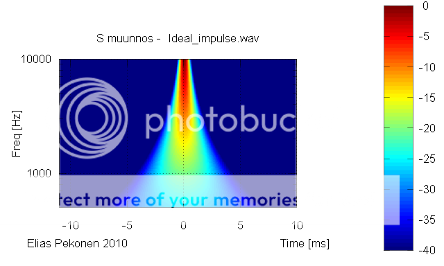
I don't think this represents ideal impulse as well as the wavelet transform does.
- Elias
If in (3.8) h(tau) is ideal impulse so h(tau) = 1 when tau = 0 and h(tau) = 0 elsewhere,
then p(tau, f) = 1, when tau = 0 and p(tau, f) = 0 elsewhere for any f.
The S transform (3.7) will then be
S(tau, f) = g(tau, f)
where g(tau, f) is the gaussian envelope multiplied by frequency (3.9).
Thus the amplitude of the S transform in case of an ideal impulse is proportional to frequency, so there will be 20dB/decade slope.
It looks like this:
I don't think this represents ideal impulse as well as the wavelet transform does.
- Elias
That is nonsense, Elias. S-Transform is a time-frequency analysis method, used to show the time varying spectral content of signals, whether impulse responses or not.
The average of the ST across all time at any chosen frequency will have the same value as the FT of the time series at that frequency, it accurately portrays the energy in the signal - to maintain the same peak amplitude while spreading the signal in frequency would misrepresent the signal's energy content, so I would say ST is a better and more accurate representation. CWT should show a similar behaviour, however CWT plots often omit energy normalisation to make them look prettier - that does not render them more accurate, one could just as easily distort the energy content of an ST plot, or any other TFR for that matter....the amplitude of the S transform in case of an ideal impulse is proportional to frequency, so there will be 20dB/decade slope.
I don't think this represents ideal impulse as well as the wavelet transform does.
Some years ago (more than ten) I took a 40 hour course at the University of Michigan in time-frequency analysis. (UM is a world leading in this technology - they have a lab which specializes in signal processing and were the key developers of synthetic aperature radar - SAR. Being dominately top secret DOD work this is not widely known.) I came away from that course with one very important realization.
These techniques are mostly aimed at "blind" signal processing such as geophysical and other situations where one cannot do a controlled input-output experiment. In audio we always have the ability to control the input signal which has a huge advantage over the "blind" situation. When one has this controlled IO ability then quite simply put the impulse response of the system tells us all that we need to know and indeed all that can be know about the system. If it's not linear then we need multi-dimensional impulse responses, ala Wiener Series and the like, but for a linear system - and all decent audio systems are very very nearly purely linear - the impulse response is all that we need to know. The rest is simplyt different ways of viewing this fundamental parameter of a system and NONE of them can show anything that cannot be seen in any other view. Spectral, temporal, wavelet, ST, all are equivalent if done correctly. Any claimed differences are just verbiage.
These techniques are mostly aimed at "blind" signal processing such as geophysical and other situations where one cannot do a controlled input-output experiment. In audio we always have the ability to control the input signal which has a huge advantage over the "blind" situation. When one has this controlled IO ability then quite simply put the impulse response of the system tells us all that we need to know and indeed all that can be know about the system. If it's not linear then we need multi-dimensional impulse responses, ala Wiener Series and the like, but for a linear system - and all decent audio systems are very very nearly purely linear - the impulse response is all that we need to know. The rest is simplyt different ways of viewing this fundamental parameter of a system and NONE of them can show anything that cannot be seen in any other view. Spectral, temporal, wavelet, ST, all are equivalent if done correctly. Any claimed differences are just verbiage.
- Status
- This old topic is closed. If you want to reopen this topic, contact a moderator using the "Report Post" button.
- Home
- Loudspeakers
- Multi-Way
- WTF!? Wavelet TransForm for audio measurements - What-is? and How-to?