The Space Egg Corporation : Bus-Bar PSU Physical Layout
Hi John
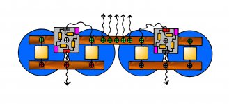
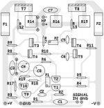
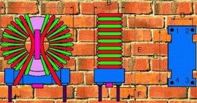
If you have the square rectifiers you could mount every thing together like this.
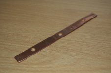
I saw from the photo your using 'eyelet solder tags' you could drill all the holes the same size as for the capacitor screws and use the same size tags for every thing.
If you would like a recommendation for the bypass capacitors on the rectifiers and reservoir caps "Let's go to work!" might be able to recommend something.
The Mr.Pink terminals are obviously the AC in.
It's a real simple but very cool layout that does away with almost all the wiring. If the rectifiers get a bit warm they'll sink in the bus-bar.
I don't know if you have a chassis for the amp yet, but this layout allows you to lay the whole assembly on its side horizontaly, and you don't have to have a massively tall case, could make it all more compact.
I kind of like compactish builds, it doesn't make much sense to me to have a huge great case just so you can stand the reservoir caps on end.
If your buying one it's usualy a lot cheaper as well.
Depends a little bit on what heatsinks are used as well.
If you have the Talema 500va toroid, I checked in the RS catalogue it's 60h x 136dia, so is probably about the same height as the diameter of the reservoir caps.
So on their side they would fit into a 2u case instead of a 3u standing up.
Don't know if your going for a 19" type case of not, they seem quite popular for amps, but again it depends on the heatsinks.
Farnell have some very nice 2u 19" cases by 'Schroff' that aren't too expensive.
Hope the drawing is helpfull
Later.........Simon.........
Yes my BR is the metal clad type
Hi John
If you have the square rectifiers you could mount every thing together like this.
I saw from the photo your using 'eyelet solder tags' you could drill all the holes the same size as for the capacitor screws and use the same size tags for every thing.
If you would like a recommendation for the bypass capacitors on the rectifiers and reservoir caps "Let's go to work!" might be able to recommend something.
The Mr.Pink terminals are obviously the AC in.
It's a real simple but very cool layout that does away with almost all the wiring. If the rectifiers get a bit warm they'll sink in the bus-bar.
I don't know if you have a chassis for the amp yet, but this layout allows you to lay the whole assembly on its side horizontaly, and you don't have to have a massively tall case, could make it all more compact.
I kind of like compactish builds, it doesn't make much sense to me to have a huge great case just so you can stand the reservoir caps on end.
If your buying one it's usualy a lot cheaper as well.
Depends a little bit on what heatsinks are used as well.
If you have the Talema 500va toroid, I checked in the RS catalogue it's 60h x 136dia, so is probably about the same height as the diameter of the reservoir caps.
So on their side they would fit into a 2u case instead of a 3u standing up.
Don't know if your going for a 19" type case of not, they seem quite popular for amps, but again it depends on the heatsinks.
Farnell have some very nice 2u 19" cases by 'Schroff' that aren't too expensive.
Hope the drawing is helpfull
Later.........Simon.........
Attachments

One more topology not considered is single secondary, using a single 80V secondary with a bridge rectifier feeding 2 filter capacitors in series with dropping resistors connected across the filter capacitors to balance the voltage and provide DC ground. The filter capacitors provide AC ground and the dropping resistors only need to be enough to balance leakage and DC offset. If an output transistor fails there needs to be a circuit to protect the filter capacitors as full DC voltage will appear on one capacitor if the supply fuse doesn't blow first. It is probably too much trouble if you are buying transformers but if you are like me and get my transformers from EOL industrial equipment it is one more option. This is a common topology in power electronic designs it is called a half bridge, it will not provide DC and it does work with audio power amplifiers and reasonably symmetric AC signals.
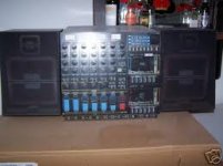
FWIW a lot of Japanese commercial equipment has a heavy duty 240V/100V isolating transformer which is just right for driving a large amplifier.
FWIW a lot of Japanese commercial equipment has a heavy duty 240V/100V isolating transformer which is just right for driving a large amplifier.
Simon/anybody?
Great diagram dude, your layout makes more sense than mine. Thanks for that!
I've fabricated a busbar prototype from 10mm copper pipe. Looking good so far but there's a bit of a hitch. My caps are snap fit, not screw fit - not a problem, I thought, just solder them to the busbar, but the copper just won't seem to take the solder.
It seems the relatively large area of copper is acting like a big heat sink and while the solder will attach itself quite happily to the pins it's refusing point blank to flow onto the copper and it's dry joint city! Thankfully I used some old ceramic caps to test it, so no harm done!
I don't want to spend more money on new caps if I can avoid it.
Any ideas?
John
Attachments
Reservoir Caps "Let's go to work!" Fixing
Hi John
Perhaps you could use some eyelet solder tags like in the amp photo.
I would pull off the plastic insulation, crimp them at the very ends of the snap-on leads and then run the solder in to the eyelet crimp.
Oriented in the right direction you could bend them outward (perhaps over a rounded object, or however) and they would be flush with underneath of bus-bars for screw fixing. I would imagine M4 would be about right if you have that size.
What diameter are the caps?
Cheers Simon...
Simon/anybody?
Great diagram dude, your layout makes more sense than mine. Thanks for that!
I've fabricated a busbar prototype from 10mm copper pipe. Looking good so far but there's a bit of a hitch. My caps are snap fit, not screw fit - not a problem, I thought, just solder them to the busbar, but the copper just won't seem to take the solder.
It seems the relatively large area of copper is acting like a big heat sink and while the solder will attach itself quite happily to the pins it's refusing point blank to flow onto the copper and it's dry joint city! Thankfully I used some old ceramic caps to test it, so no harm done!
I don't want to spend more money on new caps if I can avoid it.
Any ideas?
John
Hi John
Perhaps you could use some eyelet solder tags like in the amp photo.
I would pull off the plastic insulation, crimp them at the very ends of the snap-on leads and then run the solder in to the eyelet crimp.
Oriented in the right direction you could bend them outward (perhaps over a rounded object, or however) and they would be flush with underneath of bus-bars for screw fixing. I would imagine M4 would be about right if you have that size.
What diameter are the caps?
Cheers Simon...
Hi,
the distributed Ground connections must not serve various parts of the audio circuit.
All the Audio Grounds MUST be referenced to the same point.
It is even better to keep all the audio grounds OFF the busbar. The voltage differences along the Zero Volts busbar will contaminate the Audio Ground if placed on it.
It NEEDs a short (or longer) link from busbar to Audio Ground.
Attachments

Mark for world champion ?
Hi Metalsculptor
Thanks for the power supply input, can you draw a schematic and post it for the thread, I think it would be great to collect every power supply option under one roof.
I had wondered whether to throw in a choke reg option as Johns PSU is maybe a tad over voltage, but this may drop it too much (nice regulation though, shame about the heat).
Like your tag by the way MS, I reckon if your into engine research, and live in Melbourne, you might just have taken a wander down to Albert Park to check out the noise and root for Mark as world champion ?
With an industrial interior and an obvious love for metal I guess you might know Serra, Judd, Morris, Andre, Caro etc.
Have read a bit of your sub-woof thread, interesting stuff.
I used to have access to machine tools and bemoaned their departing with a change of work, but have now enjoyed a renaissance of metal sculpting myself, and have found that I love using favorite files from the toolbox as much as listening to favorite toonz from the collection (if I lost my 40 year old magneto file, I would be heart broken and would probably find no replacement).
The case for my last diyAudio project was made from:-
*A building contractors roadsign.
*A Norwegan lacquered aluminium fruit bowl.
*Aluminium channel from a skipped take-out store counter.
*Sheilding panel from a cell phone company tower.
*Panel from 70's synthesiser.
And a few other bits to stick it all together.
Would love to find one of those Japanese transformers, as am currently doing a turntable refurbishment, and am considering doing an ARMAGEDDON power supply clone.
Would love also to do a tone-arm build.
Cheers. Speak to you soon. Simon... .........
One more topology not considered is single secondary, using a single 80V secondary with a bridge rectifier feeding 2 filter capacitors in series with dropping resistors connected across the filter capacitors to balance the voltage and provide DC ground. The filter capacitors provide AC ground and the dropping resistors only need to be enough to balance leakage and DC offset. If an output transistor fails there needs to be a circuit to protect the filter capacitors as full DC voltage will appear on one capacitor if the supply fuse doesn't blow first. It is probably too much trouble if you are buying transformers but if you are like me and get my transformers from EOL industrial equipment it is one more option. This is a common topology in power electronic designs it is called a half bridge, it will not provide DC and it does work with audio power amplifiers and reasonably symmetric AC signals.
FWIW a lot of Japanese commercial equipment has a heavy duty 240V/100V isolating transformer which is just right for driving a large amplifier.
Hi Metalsculptor
Thanks for the power supply input, can you draw a schematic and post it for the thread, I think it would be great to collect every power supply option under one roof.
I had wondered whether to throw in a choke reg option as Johns PSU is maybe a tad over voltage, but this may drop it too much (nice regulation though, shame about the heat).
Like your tag by the way MS, I reckon if your into engine research, and live in Melbourne, you might just have taken a wander down to Albert Park to check out the noise and root for Mark as world champion ?
With an industrial interior and an obvious love for metal I guess you might know Serra, Judd, Morris, Andre, Caro etc.
Have read a bit of your sub-woof thread, interesting stuff.
I used to have access to machine tools and bemoaned their departing with a change of work, but have now enjoyed a renaissance of metal sculpting myself, and have found that I love using favorite files from the toolbox as much as listening to favorite toonz from the collection (if I lost my 40 year old magneto file, I would be heart broken and would probably find no replacement).
The case for my last diyAudio project was made from:-
*A building contractors roadsign.
*A Norwegan lacquered aluminium fruit bowl.
*Aluminium channel from a skipped take-out store counter.
*Sheilding panel from a cell phone company tower.
*Panel from 70's synthesiser.
And a few other bits to stick it all together.
Would love to find one of those Japanese transformers, as am currently doing a turntable refurbishment, and am considering doing an ARMAGEDDON power supply clone.
Would love also to do a tone-arm build.
Cheers. Speak to you soon. Simon...
.........Avoid using a choke, load regulation will suffer and the no load voltage will hardly change use a small bucking transformer on the primary or if you are using toroidal transformers it is easy to tap the secondary or wind a few turns of heavy wire around the core and connect these in series antiphase with the secondary. Toroidal transformers are my favourite scrounge as they are so easy to change voltage on. To work out how many turns, wrap 2 turns of any wire around the core and measure the voltage, a 300Va transformer will have about 1.5V so for every 1.5V reduction in AC output 2 turns are required in this example.I had wondered whether to throw in a choke reg option as Johns PSU is maybe a tad over voltage, but this may drop it too much (nice regulation though, shame about the heat).
Same here so I constructed a place to house them and bought some for home. My workshop is bigger than the house, a man's got to get his priorities right.I used to have access to machine tools and bemoaned their departing with a change of work, but have now enjoyed a renaissance of metal sculpting myself.
I will get around to sketching a schematic, drawing software is not something I normally use, I should download a simulator and draw it in that. Thank for the interest in the sub, I have found a suitable vessel to house the driver and it will be quite striking.
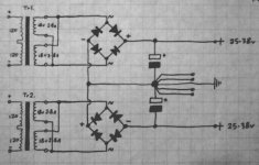
Schematic
Hi Metalsculptor
I have no drawing software or simulator, or even scanner & printer.
I just draw on paper and photograph, and sometimes colour in with the computer, old-school, always have to have pencil & paper for notes though.
You didn't tell me if your rooting fo Mark in the championship ?
Cheers Simon...
I will get around to sketching a schematic, drawing software is not something I normally use, I should download a simulator and draw it in that.
Hi Metalsculptor
I have no drawing software or simulator, or even scanner & printer.
I just draw on paper and photograph, and sometimes colour in with the computer, old-school, always have to have pencil & paper for notes though.
You didn't tell me if your rooting fo Mark in the championship ?
Cheers Simon...
Attachments
Don't. The two fuses must remain where they are, because they protect the transformer secondaries. Removing those fuses will remove the protection from faults in the rectifiers, capacitors and the wiring to them.First:
Move the two fuses.
Yes, that should be added.One goes in the mains primary circuit.
I would rate that as a "nice-to-have". It helps to find out in which channel a fault occurs, if it only affects one of them.One more goes in the secondary circuit AFTER the main smoothing caps for every polarity.
everywhere. You won't find any fast blow fuse that protects the semiconductors from destruction and lets transient signals pass unhindered at the same time.Use a close rated slow blow...


Back To The Workshop
Hi John
Hows the power supply build going ?
Just thought, if the assembly isn't rigid enough without screw tops,
You could maybe cut strips of insulator with holes in and bolt 4 of them across the ends of the bus-bars ?
Cheers Simon...
Back to the workshop.
Cheers man!
Hi John
Hows the power supply build going ?
Just thought, if the assembly isn't rigid enough without screw tops,
You could maybe cut strips of insulator with holes in and bolt 4 of them across the ends of the bus-bars ?
Cheers Simon...
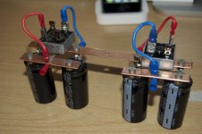
'tis built!
Hey Simon.
It's coming along very nicely thanks! I finished it off last night. The bus bars are made of pressed 10mm copper pipe. It was pretty fiddly but looks pretty good. To be honest it's the first thing of this nature I've ever fabricated since school and I was pleasantly surprised with the outcome
I plugged in and tested it last night, and as expected there is +62v and -62v on the respective rails. It's a little annoying as I expected 56v from the 40v secondaries however our mains comes in at 240v as apposed to the 230 the trafo is rated for so I'm getting 46v at the secondaries - hence my 'voltage reduction' thread! Although Mooly reckons 62v should be OK for my amps which require 45-55v as long as my caps are suitably rated. What do you think?
Underneath each BR there is a 2k2 resistor in parallel with the caps (the capacitor drain after power-off was the firs thing I tested). All in all it feels pretty solid, inevitably there's a little bit of flex but I can't imagine that would be a problem?
No snubbing caps yet as I've yet to ascertain the optimum rating, was thinking along the lines of 0.1uf on the BR and 10uf on the smoothing caps.
So what do you reckon - not bad for an amp newbie!
John
Hey Simon.
It's coming along very nicely thanks! I finished it off last night. The bus bars are made of pressed 10mm copper pipe. It was pretty fiddly but looks pretty good. To be honest it's the first thing of this nature I've ever fabricated since school and I was pleasantly surprised with the outcome
I plugged in and tested it last night, and as expected there is +62v and -62v on the respective rails. It's a little annoying as I expected 56v from the 40v secondaries however our mains comes in at 240v as apposed to the 230 the trafo is rated for so I'm getting 46v at the secondaries - hence my 'voltage reduction' thread! Although Mooly reckons 62v should be OK for my amps which require 45-55v as long as my caps are suitably rated. What do you think?
Underneath each BR there is a 2k2 resistor in parallel with the caps (the capacitor drain after power-off was the firs thing I tested
). All in all it feels pretty solid, inevitably there's a little bit of flex but I can't imagine that would be a problem?No snubbing caps yet as I've yet to ascertain the optimum rating, was thinking along the lines of 0.1uf on the BR and 10uf on the smoothing caps.
So what do you reckon - not bad for an amp newbie!
John
Attachments
PSU DONE !
Hi John
Looks EX, just the job!
I could post a drawing of the snubbing stuff, but my drawing process is a bit weird.
Believe it or not, I don't have a scanner or printer.
I draw my stuff on paper, photograph it and then sometimes colour it in using the paint bucket fill on my PC, like the bus-bar layout.
I have a PC drawing tablet, but still prefer paper and ink !
If you search on the site or just google (there's some good stuff @ audio asylum) 'Reverse Recovery Spike Filter' you will find it all discussed regarding diode snubbing.
What is your prefered component supplier ?
I mostly use RS, CPC or Farnell, RS have every thing, but sometimes CPC are good and beat RS on prices.
I would use some plastic film caps across the 4700uF's, and some small plastic films or ceramics across the diodes.
If you let me know your prefered supplier, I could recommend a part #.
Check out the 'RRSP' stuff, a few 1uF plastic film caps are usualy used here along with a couple of 20ohm power resistors.
One comment on the PSU and for general use of eyelet tags anywhere, I pull off the plastic bits, crimp the wire and then run solder in for long term reliability and low resistance.
Also I would recommend at the same time as soldering the caps across the diodes, also solder the wires to the rectifier tags and use as thicker cable as possible or doubled up cable. Also soldering to the eyelets connecting to the bus-bar, this ensures very low resistance.
I would also drill some more holes either side of the central ground hole.
The grounds from your RCA input sockets can both go on the middle hole and close by each side should be two more holes, one for PSU 0volts return from amps, and one for speaker 0volts from prehistoric 4mm binding posts (or 'Neutrik Speakon' connectors if you have any sense !!!), making 5 holes in all as in my drawing. This makes it easier to connect up all these returns in a good low resistance way.
You could also make a nice DIY mains filter for the transformer primary. I am making mains filters for loads of stuff at the moment, and a DIY one can be made much better than the crapy IEC input filters which are sold that are way over priced.
Cheers for now. Simon...
Hey Simon.
So what do you reckon - not bad for an amp newbie!
John
Hi John
Looks EX, just the job!
I could post a drawing of the snubbing stuff, but my drawing process is a bit weird.
Believe it or not, I don't have a scanner or printer.
I draw my stuff on paper, photograph it and then sometimes colour it in using the paint bucket fill on my PC, like the bus-bar layout.
I have a PC drawing tablet, but still prefer paper and ink !
If you search on the site or just google (there's some good stuff @ audio asylum) 'Reverse Recovery Spike Filter' you will find it all discussed regarding diode snubbing.
What is your prefered component supplier ?
I mostly use RS, CPC or Farnell, RS have every thing, but sometimes CPC are good and beat RS on prices.
I would use some plastic film caps across the 4700uF's, and some small plastic films or ceramics across the diodes.
If you let me know your prefered supplier, I could recommend a part #.
Check out the 'RRSP' stuff, a few 1uF plastic film caps are usualy used here along with a couple of 20ohm power resistors.
One comment on the PSU and for general use of eyelet tags anywhere, I pull off the plastic bits, crimp the wire and then run solder in for long term reliability and low resistance.
Also I would recommend at the same time as soldering the caps across the diodes, also solder the wires to the rectifier tags and use as thicker cable as possible or doubled up cable. Also soldering to the eyelets connecting to the bus-bar, this ensures very low resistance.
I would also drill some more holes either side of the central ground hole.
The grounds from your RCA input sockets can both go on the middle hole and close by each side should be two more holes, one for PSU 0volts return from amps, and one for speaker 0volts from prehistoric 4mm binding posts (or 'Neutrik Speakon' connectors if you have any sense !!!), making 5 holes in all as in my drawing. This makes it easier to connect up all these returns in a good low resistance way.
You could also make a nice DIY mains filter for the transformer primary. I am making mains filters for loads of stuff at the moment, and a DIY one can be made much better than the crapy IEC input filters which are sold that are way over priced.
Cheers for now. Simon...
Attachments
Hi John
Looks EX, just the job!
Cheers!
I could post a drawing of the snubbing stuff, but my drawing process is a bit weird.
I like weird...
Believe it or not, I don't have a scanner or printer.
I draw my stuff on paper, photograph it and then sometimes colour it in using the paint bucket fill on my PC, like the bus-bar layout.
I have a PC drawing tablet, but still prefer paper and ink !
The busbar diagram doesn't look hand drawn...it's rather good! Nothing wrong with a bit of old skool - that's why I'm building a powerful trannie amp rather than a gainclone!
The whole project stemmed from wanting a high spec amp to play my vinyl collection (now I'm showing my age
If you search on the site or just google (there's some good stuff @ audio asylum) 'Reverse Recovery Spike Filter' you will find it all discussed regarding diode snubbing.
Found it - will make some good bedtime reading
What is your prefered component supplier ?
I mostly use RS, CPC or Farnell, RS have every thing, but sometimes CPC are good and beat RS on prices.
I've used RS & CPC for the majority of the components for this amp, but I found Rapid to be V good + the shipping is free if you spend over 30 notes. If you want a few quids worth of components, Bitsbox and Bowood are good and the carriage is cheap - £1.50 per order for Bitsbox and Royal mail prices at Bowood (£1.65 minimum p&P) plus neither have a minimum order and they are pretty good on price
If I'm desperate I'll go to my local Maplin....
I would use some plastic film caps across the 4700uF's, and some small plastic films or ceramics across the diodes.
If you let me know your prefered supplier, I could recommend a part #.
I have a parts list with Rapid at the moment for my GC so that would be ideal, thanks!
Check out the 'RRSP' stuff, a few 1uF plastic film caps are usualy used here along with a couple of 20ohm power resistors.
One comment on the PSU and for general use of eyelet tags anywhere, I pull off the plastic bits, crimp the wire and then run solder in for long term reliability and low resistance.
Good call - I just like to look at the pretty colours.....
Also I would recommend at the same time as soldering the caps across the diodes, also solder the wires to the rectifier tags and use as thicker cable as possible or doubled up cable. Also soldering to the eyelets connecting to the bus-bar, this ensures very low resistance.
Do you have a solder fetish?
I would also drill some more holes either side of the central ground hole.
The grounds from your RCA input sockets can both go on the middle hole and close by each side should be two more holes, one for PSU 0volts return from amps, and one for speaker 0volts from prehistoric 4mm binding posts (or 'Neutrik Speakon' connectors if you have any sense !!!), making 5 holes in all as in my drawing. This makes it easier to connect up all these returns in a good low resistance way.
If the V- return from the amp goes to the ground then what connects to the PSU negative rail? Also, the amp PCB has pos & neg points for the speakers and inputs - are you suggesting I use the ground instead of the PCB neg/gnd connections or as well as? Obviously the amp's main GND connection will go to the ground rail (PCB layout attached)
You could also make a nice DIY mains filter for the transformer primary. I am making mains filters for loads of stuff at the moment, and a DIY one can be made much better than the crapy IEC input filters which are sold that are way over priced.
Can you recommend a link to schematic/PCB/project
Cheers for now. Simon...
Cheers yourself!
P.S. check out my the post I'm doing about my first amp - it's, uh, different....
P.S.S. are you building anything at the moment?
P.S.S.S. what's your preferred method for producing PCBs - have you had any experience with Press-n-peel?
Attachments
Yes, I am building quite a few things at the moment.
Hi John
Yes, I am building quite a few things at the moment.
I don't have photos of them all at the present time.
Maybe I will take some during the week and post them so you can see what I'm up to.
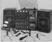
I do have photos of this which I previously sent to a NZ friend of mine.
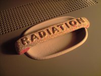
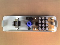
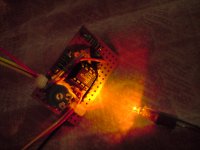
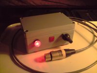
I call it 'The Radiation Reverb'
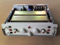
It's an analogue reverb with passive EQ circuit & built-in wet/dry control.
Have made it so the operative knobs are lit-up by LED's behind the dial markings, according to the function selected by the central selector switch. It looks pretty cool in dimly lit studios.
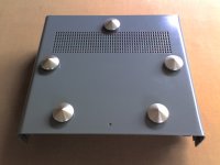
A friend of mine gave me the handle which goes in the top of the case.
They thought I would like it, which I do very much, they saved it from a junk 1950's electric cooker they happened accross.
Which of course gave me the idea for the reverb's name, apt I think due to the acoustic/mechanical radiation by which the reverb operates.
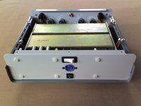
Have had it all working on the bench with wires everywhere, and it's now getting shoved into it's case (it sounds amazing).
It's completed my collection of analogue reverbs.
I also have a 1960's 'WEM Copycat' tape delay/reverb (heavily modded).
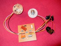
And a DIY multi-tap electronic analogue delay/reverb based on the BBDL (Bucket Brigade Delay Line) principle.
Just forgot, I don't have a plate reverb, like the Beatles at Abbey Road, but maybe I could make a DIY miniature one like the 'EMT Plate Reverb' next (Oh dear another project !).
There's also another type, which is basicly a speaker & microphone inside an acoustic chamber (Replicating this in your bathroom or other reverberant space with a speaker and microphone is quite easy).
Here's a few photos.
Cheers Simon...
...!
Hi John
Yes, I am building quite a few things at the moment.
I don't have photos of them all at the present time.
Maybe I will take some during the week and post them so you can see what I'm up to.
I do have photos of this which I previously sent to a NZ friend of mine.
I call it 'The Radiation Reverb'
It's an analogue reverb with passive EQ circuit & built-in wet/dry control.
Have made it so the operative knobs are lit-up by LED's behind the dial markings, according to the function selected by the central selector switch. It looks pretty cool in dimly lit studios.
A friend of mine gave me the handle which goes in the top of the case.
They thought I would like it, which I do very much, they saved it from a junk 1950's electric cooker they happened accross.
Which of course gave me the idea for the reverb's name, apt I think due to the acoustic/mechanical radiation by which the reverb operates.
Have had it all working on the bench with wires everywhere, and it's now getting shoved into it's case (it sounds amazing).
It's completed my collection of analogue reverbs.
I also have a 1960's 'WEM Copycat' tape delay/reverb (heavily modded).
And a DIY multi-tap electronic analogue delay/reverb based on the BBDL (Bucket Brigade Delay Line) principle.
Just forgot, I don't have a plate reverb, like the Beatles at Abbey Road, but maybe I could make a DIY miniature one like the 'EMT Plate Reverb' next (Oh dear another project !).
There's also another type, which is basicly a speaker & microphone inside an acoustic chamber (Replicating this in your bathroom or other reverberant space with a speaker and microphone is quite easy).
Here's a few photos.
Cheers Simon...
Attachments
-
 P201209_19.23.JPG917.1 KB · Views: 135
 -
 30-06-07_1438.jpg219.2 KB · Views: 90
 -
 30-06-07_1448.jpg200.7 KB · Views: 103
 -
 30-06-07_1452.jpg257 KB · Views: 97
 -
 30-06-07_1511.jpg248 KB · Views: 92
 -
 30-06-07_1518.jpg202.9 KB · Views: 62
 -
 DSCF2509 (Large).jpg173.9 KB · Views: 65
 -
 P271209_15.09.JPG786.3 KB · Views: 62
 -
 P291209_21.28.JPG760.6 KB · Views: 67
Radiation Reverb Build
Hi John
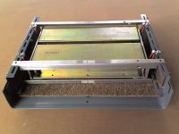
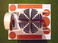
Yes the 'Radiation' handle is the biz.
The mechanical reverb boxes suspended on the red 'o' rings in the photo, can't move out of the correct hanging position due to the aly angle pieces around them, but its best to move the unit horizontaly, so the handle on top which I guess is unusual, is very practical in this case.
Hope it's going well on the diy.
I am looking to build a new amp at the moment too.
Have been doing some CAD work on it to get a sense of the PSU layout and stuff (Cardboard Aided Design).
Just found some very cheap MOSFETS, so am thinking to buy a load of them before they sell out.
Turntable refurb and new RIAA preamp as well, tooooo many projects !
Cheers Simon...
Nice pics Simon, so did you hand build all that equip? Love the Radiation handle!
Hi John
Yes the 'Radiation' handle is the biz.
The mechanical reverb boxes suspended on the red 'o' rings in the photo, can't move out of the correct hanging position due to the aly angle pieces around them, but its best to move the unit horizontaly, so the handle on top which I guess is unusual, is very practical in this case.
Hope it's going well on the diy.
I am looking to build a new amp at the moment too.
Have been doing some CAD work on it to get a sense of the PSU layout and stuff (Cardboard Aided Design).
Just found some very cheap MOSFETS, so am thinking to buy a load of them before they sell out.
Turntable refurb and new RIAA preamp as well, tooooo many projects !
Cheers Simon...
Attachments
- Status
- This old topic is closed. If you want to reopen this topic, contact a moderator using the "Report Post" button.
- Home
- Amplifiers
- Power Supplies
- Dual PSU layout - how does this look?