They sound really awesome, no one believe when see the ribbon moving, im with problem some problems ($$) on project of ribbon supports, a guy said that will cost arround 80USD to make 4 teflon supports for the aluminium ribbon, im thinking now on some cheaper material, later i can put a gold coated pcb to act as ribbon contacts.
How this will be a wide range speaker (arround 300~20khz) im with some doubts on back filling of speaker, with no filling thats to much distortion from the chamber, i tried with 25mm 33D density foam and got a good result, i thinking on make 3 o 4 damping layers: 33d foam, glass fiber and cotton all to prevent any refraction and distortion from back walls. This is the problem on use non dipole ribbon tweeter
About the weigh, only ribbons are arround 30 kg each, the cabinets idk yet, but with the amount of mdf used on they i can say arround 80 kg each, aaaah i forgot... more 10kg of 6" midbass!
Murilo
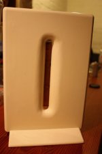
The back chamber is used to fix the speaker on cabinet, and helps to hold, concentrate and increase the magnetic field through the gap between the magnets.
Without this chamber, on a old tv (crt) i got a green cloud from the screen while the magnets was 2,5m far from tv.
With this one, its safe put all only 40cm from tv and i noted a huge increase on magnetic field, but sadly i dont make any measure from the response and efficiency of it.
About the audio, if i make the ribbon tweeter as dipole i have to put the speaker at minimum 1m from the back wall, and i don't have enough space on the living room, so encapsulate the back of it starts be a positive point on my project.
It looks like that should work well.
Denis
Thanks.
I think that I should try some femm simulations to find out the specifics.
B.L.
Ribbon thickness follow up
This post is a follow up on the discussion about ribbon thickness that was started around post #648.
I have measured the frequency response of two modified UR2 ribbon tweeters.
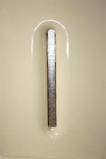
One has a 9 microns thick aluminium ribbon whereas the other has a 1 micron thick ribbon. I am not sure about the thickness of the 1 micron foil, but it is very fragile.I used the Silver Leaf from Mona Lisa.
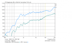
The first picture below shows the frequency response of the two drivers without the impedance transformer. Instead , a 100 ohms resistor was used, such that the electrical resistance of the two ribbons is very close. The measurement was made at a distance of 52 cm. I somewhat calibrated the display of the FR such that the level of the UR2/9microns reaches 90 db at 10KHz. The one micron ribbon tweeter has a much higher sensitivity - about 10 db more. It has a strong cavity resonance at 1500 Hz. The other tweeter does not show such a strong resonance because I added cotton inside the cavity.
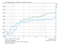
The second picture shows the frequency response of the two drivers with the original impedance transformer (No 100 ohms resistors). This time the 1 micron tweeter is less sensitive than the 9 microns one. The reason I guess is that the UR2 transformer is not designed for the higher resistance of the thinner ribbon .
Bruno
This post is a follow up on the discussion about ribbon thickness that was started around post #648.
I have measured the frequency response of two modified UR2 ribbon tweeters.
An externally hosted image should be here but it was not working when we last tested it.
. One has a 9 microns thick aluminium ribbon whereas the other has a 1 micron thick ribbon. I am not sure about the thickness of the 1 micron foil, but it is very fragile.I used the Silver Leaf from Mona Lisa.
An externally hosted image should be here but it was not working when we last tested it.
)The first picture below shows the frequency response of the two drivers without the impedance transformer. Instead , a 100 ohms resistor was used, such that the electrical resistance of the two ribbons is very close. The measurement was made at a distance of 52 cm. I somewhat calibrated the display of the FR such that the level of the UR2/9microns reaches 90 db at 10KHz. The one micron ribbon tweeter has a much higher sensitivity - about 10 db more. It has a strong cavity resonance at 1500 Hz. The other tweeter does not show such a strong resonance because I added cotton inside the cavity.
The second picture shows the frequency response of the two drivers with the original impedance transformer (No 100 ohms resistors). This time the 1 micron tweeter is less sensitive than the 9 microns one. The reason I guess is that the UR2 transformer is not designed for the higher resistance of the thinner ribbon .
Bruno
Attachments
Hello Brunob,
Interesting the amt of gain in efficiency !
While there is an obvious benefit in efficiency by running a lightweight ribbon, there is also a negative in sonics from going 2 light, the driver will lack percussive energy, instruments will sound thin with no real impact, toy like in nature, like anything else, you will have to find a proper balance between the 2 ......
regards,
Hi
You don't want to use Teflon, it is impossible to glue and expensive. Use lexan or PVC you can buy sheets and cut by hand or mill
You don't want to use Teflon, it is impossible to glue and expensive. Use lexan or PVC you can buy sheets and cut by hand or mill
They sound really awesome, no one believe when see the ribbon moving, im with problem some problems ($$) on project of ribbon supports, a guy said that will cost arround 80USD to make 4 teflon supports for the aluminium ribbon, im thinking now on some cheaper material, later i can put a gold coated pcb to act as ribbon contacts.
How this will be a wide range speaker (arround 300~20khz) im with some doubts on back filling of speaker, with no filling thats to much distortion from the chamber, i tried with 25mm 33D density foam and got a good result, i thinking on make 3 o 4 damping layers: 33d foam, glass fiber and cotton all to prevent any refraction and distortion from back walls. This is the problem on use non dipole ribbon tweeter
About the weigh, only ribbons are arround 30 kg each, the cabinets idk yet, but with the amount of mdf used on they i can say arround 80 kg each, aaaah i forgot... more 10kg of 6" midbass!
Murilo
Hi
You don't want to use Teflon, it is impossible to glue and expensive. Use lexan or PVC you can buy sheets and cut by hand or mill
Was a mistake on my spelling, i was thinking to drill a nylon block to hold ribbons.
Sorry
I hope i have some news soon.
FEMM can be wrong
I measured the magnetic fields using a Hirst gaussmeter of long and short magnets systems. I did NOT observe a strong decrease the magnetic field in the ribbon gap for a long versus a short system. Seems that FEMM is wrong here.
Bruno
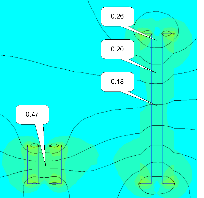
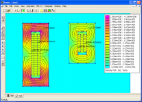
Here is the first simulation.
On the left, two 5x1.5 cm neodymium magnets. On the right, two 20x1.5 cm neodymium magnets. On the left, the predicted B is 0.47 T (tesla) for the ribbon gap. On the right, 0.18 T.
According to the simulation, there is a strong decrease of the magnetic field in the ribbon gap.
I measured the magnetic fields using a Hirst gaussmeter of long and short magnets systems. I did NOT observe a strong decrease the magnetic field in the ribbon gap for a long versus a short system. Seems that FEMM is wrong here.
Bruno
Re: Long short magnet length field strength
I did a couple of Femm simulations to try to figure out why it should show reduced field strength in the gap with longer magnets.
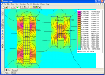
The first attached picture is my Femm of long and short ribbons and, as mentioned in previous posts, it shows reduced gap field strength for the long ribbon. This first simulation did not have any cross pieces between the two pole pieces.
The second simulation is the same setup but I've added cross bars top and bottom. This simulation shows the same gap field strength for the long and short ribbons.
I can't explain why adding cross bars makes this difference.
Using the cross bars also significantly increases the field strength because it completes the magnetic circuit between the pole pieces.
I did a couple of Femm simulations to try to figure out why it should show reduced field strength in the gap with longer magnets.
The first attached picture is my Femm of long and short ribbons and, as mentioned in previous posts, it shows reduced gap field strength for the long ribbon. This first simulation did not have any cross pieces between the two pole pieces.
The second simulation is the same setup but I've added cross bars top and bottom. This simulation shows the same gap field strength for the long and short ribbons.
I can't explain why adding cross bars makes this difference.
Using the cross bars also significantly increases the field strength because it completes the magnetic circuit between the pole pieces.
Attachments
............ it completes the magnetic circuit between the pole pieces.
magnet field is always "complete", so to speak
well, I know you said magnet "curcuit"
but "completion" through air uses some more strength
backfield through air is also longer
directing the field through iron keeps more of the dtrength in the magnets, and front field, where its needed
some even believe that the back iron should have a big round shape similar to the natural field shape
Feastrex fullrange driver is a good example of that theory
Today I do not believe thats true at all
It will only cause using way too much iron
I now believe in using copper plate to keep more of the back field in the iron
What is the optimum distance between the x-bars?
It depends on the strength of the magnets and the size of the steel. You want to have the cross pieces close enough so that the field in the steel pole pieces and cross bars does not cause it to saturate. You want to keep below something like 2.4 Tesla in 1018 steel.
tinitus - I'm not sure what you are doing with the copper plate. Since copper is nonmagnetic it shouldn't affect the static magnetic fields caused by the magnets.
tinitus - I'm not sure what you are doing with the copper plate.
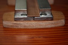
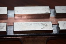
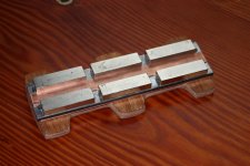
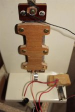
mind you, its just an experiment, and using materials I had around the place
now Im at it, a few more pictures
still some things to do, like mounting felt etc
but the copper does seem to have an effect on magnet field
both on strength and shape
but a different design from what you are using in sims
its more like when building planars
I expect it to have less edge diffraction this way
and having no problems with keeping the magnets fixed, its also simple to build
Attachments
tinitus - Very interesting. How did you determine that the size and shape of the magnetic field had been changed by the copper strip? Are you measuring or simulating? If you are measuring, what are you using to measure? I'm interested in getting something to measure with but I'm not sure what to look for.
Do you think the spaces between adjacent magnets causes the field strength between the poles to be unsymmetrical? I think you might get a more uniform field if the magnets actually touched each other.
Thanks,
Denis
Do you think the spaces between adjacent magnets causes the field strength between the poles to be unsymmetrical? I think you might get a more uniform field if the magnets actually touched each other.
Thanks,
Denis
- Status
- This old topic is closed. If you want to reopen this topic, contact a moderator using the "Report Post" button.
- Home
- Loudspeakers
- Planars & Exotics
- Another DIY Ribbon thread