Gary,
tribute is to Dr. Uli Brueggemann (diyA member) :
(((acourate)))® - Room Correction, Speaker Optimization and Sound Improvement
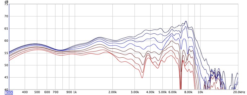
TD15M unsmoothed frequency response looks like this in HolmImpulse, with different gating before the wiggle, after it, and finally just before the first reflections. Pretty amazing, too! Note I tilted the phase up to higher frequencies in the graph to compensate the shift of acoustic centers with frequency which makes the driver non minimum-phase. HolmImpulse adjusts to the highest peak (among other options) to determine the phase, upon import.
Klaus
tribute is to Dr. Uli Brueggemann (diyA member) :
(((acourate)))® - Room Correction, Speaker Optimization and Sound Improvement
TD15M unsmoothed frequency response looks like this in HolmImpulse, with different gating before the wiggle, after it, and finally just before the first reflections. Pretty amazing, too! Note I tilted the phase up to higher frequencies in the graph to compensate the shift of acoustic centers with frequency which makes the driver non minimum-phase. HolmImpulse adjusts to the highest peak (among other options) to determine the phase, upon import.
Klaus
Attachments
I now listened to the undamped IR in the same way as mentioned, the prominent difference is that there is clearly a hall-of-mirrors sound to it from all the scattered reflections inside the cabinet. I still think the wiggle @ 2.5ms could be the damped (lowpass-filtered) rebound of the backwave impulse hitting back through the light cone which seems to allow much of the energy to leak through. It might also come from back panel and cabinet motion leaking through around the cabinet to the mike, bounce from the exited floor into mic-stand etc.
Klaus
Klaus
Last edited:
Some REW fun with those impulses:


Your start and stop time for the "less damping" is different than from the other 2. I don't know how much that effects what REW generates, but this is with all the start and stop times the same to generate the spectrograms.
Dan
Your start and stop time for the "less damping" is different than from the other 2. I don't know how much that effects what REW generates, but this is with all the start and stop times the same to generate the spectrograms.
Dan
Last edited:
Looks like I'm gonna have to take this fight outside.
Seems to be needed - otherwise you may walk in circles.
Possibly you do not stack the mid an the woofer if thats possibly - there might be some interaction better to exclude.
Its great that you provide files for your measurements and its great and very interesting analysis we see done with this.

Michael
I now listened to the undamped IR in the same way as mentioned, the prominent difference is that there is clearly a hall-of-mirrors sound to it from all the scattered reflections inside the cabinet. I still think the wiggle @ 2.5ms could be the damped (lowpass-filtered) rebound of the backwave impulse hitting back through the light cone which seems to allow much of the energy to leak through. It might also come from back panel and cabinet motion leaking through around the cabinet to the mike, bounce from the exited floor into mic-stand etc.
Klaus
Klaus, what is needed to do such listening tests? did you already outline that elsewhere?
Michael
That blip at 2.15 ms still looks the same to me.
Just look at the positive side of things - this very reflection did *not* come alive with the dampening material removed.
Meaning - there still is good chance its a measurement issue and you are *way less* in troubles than otherwise.
")
Which were the exact settings for impulse response measurement you use?
Michael
What happens if you add a low pass filter to get that break up out of the measurement?
Dan
Depends, I'd say.
*If* we look at break up as to be a time delay effect (standing waves of different patterns building up in cone due to low internal dampening of the diaphragm material and suboptimal termination at the surround) my CMP concept applies.
*BUT*, also look at the discussion about CMP some postings back where no agreement on the issue and implications of CMP could be established.
My own point would be that for a rough tonal balance you can EQ (pretty successfully) as much as you like - but regarding CMP distortion still coming along - well - there simply is no treatment whatsoever.
Low pass filter is a good thing anyway - low signal > low distortion
Same if you look at the 2.3ms reflection in case its *not* a measurement artifact.
Michael
Last edited:
Gary called today, and I asked him to compare the magnitudes of the first arrival to the 2.5 mSec or so reflection. The reflection is about 22 dB down, not too bad, but it would be nice to remove it, if possible.
Interestingly, the reflection is inverted relative to the first arrival. In my experience, floor bounces and wall reflections are the same polarity as the first arrival wave, which begs the question of where it is coming from. It could be from the rear wall; the timing is about right, and the wave from the back of the woofer is of course inverted. Gary mentioned the magnitudes of the 2.5 mSec reflection are about the same with or without the Bonded Logic damping pads, which is odd, since most of the energy of the impulse is at high frequencies, and that's also where damping fill is also most effective.
Time to change approaches. There is a possibility the "reflection" is actually diffraction off the rear of the cabinet - the timing would be about right. So, while we talked on the phone, I suggested that Gary do another set of measurements - keep the microphone right where it is, but make another two measurements, rotating the cabinets first to 90 degrees, and then 45 degrees. If it really is diffraction, the timing between the first arrival and the "reflection" should be substantially altered - for the 90 degree rotation, the time delay should be cut in half. I told Gary to look not at the main group of clutter, but compare the rise time portions of the first arrival and the "reflection", and work out the delays between the two. If the delay significantly changes with measurement angle, it is on the outside of the cabinet, not the inside.
Guess what - that's what happened. With the speaker rotated 90 degrees, the "reflection" now arrived about 1.3 to 1.4 mSec after the first arrival, although both are significantly low-passed by the 90 degree off-axis measurement. The 45 degree measurement is essentially buried by clutter, making estimation of the delay difficult.
My best guess is the artifact is indeed a diffraction from the rear edge of the cabinet, which is a much sharper edge than the front radiused corners. I suggested two approaches to Gary: half-pipes to round off the rear edges, and/or covering the sides and rear with thick felt. The effectiveness of these approaches can be compared by looking at the magnitude (and timing) of the 2.5 mSec artifact. I am doubtful it has anything to do with the driver, which would have to have a very large frame in order to produce a reflection that much later than the first arrival.
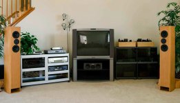
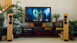
My postings have a been a little quiet recently - for the last week, I've been very busy with re-doing the HT system, which entailed a complete tear-down and re-building of both audio and video systems. In North America, we don't use SCART video connections, so the old system was a maze of composite (NTSC), S-Video, Component (480i & 1080i), digital audio, and analog audio connections. Now there's just one set of Component connections from the Comcast DVR, while the new items use Atlona HDMI 1.4 cabling. I'm already getting acquainted with the little handshake quirks of HDMI - it's a little too smart for its own good, like the player refusing to accept a disk if the TV is turned off.
New stuff: Panasonic TC-P58VT25 1080P 3D TV, Panasonic DMP-BDT300 Blu-Ray player, Dynaudio SC X center speaker, and assorted Salamander rack systems. The now-antique Denon 2805 is pre-HDMI, only has optical and coax digital inputs, and as a result, does not support SACD, DVD-A, and the new lossless Blu-Ray audio formats, which exceed the bandwidth of the old S/PDIF transmission format. So it is next in line for replacement, along with an OPPO player to supplement the Panasonic BDT-300, which annoyingly does not play SACD or DVD-A audio discs. The OPPO will probably end up being the transport and disk-spinner for the all-triode side of things, along with the capability to play 1080/24P Blu-Ray and scale-up legacy DVD's.
Projectors? Not until I build a dedicated video room in the basement - a project many years away, if ever. In the meantime I can enjoy 3D Blu-Ray discs - the German disc has a very good 3D effect, by the way, more natural and realistic than Avatar. The next immediate task is finish the changeover switches for the Ariels so they can switched between the HT amplifier and 300B triode system - the crossovers are lurking under the wicker baskets, and need a rebuilding so they look better, are more robust, and have the four-pole, double-throw changeover switches installed. (Grounds need to be switched as well as signal, so the two sets of amplifiers are never cross-connected.)
Here's the Before and After pictures:
Interestingly, the reflection is inverted relative to the first arrival. In my experience, floor bounces and wall reflections are the same polarity as the first arrival wave, which begs the question of where it is coming from. It could be from the rear wall; the timing is about right, and the wave from the back of the woofer is of course inverted. Gary mentioned the magnitudes of the 2.5 mSec reflection are about the same with or without the Bonded Logic damping pads, which is odd, since most of the energy of the impulse is at high frequencies, and that's also where damping fill is also most effective.
Time to change approaches. There is a possibility the "reflection" is actually diffraction off the rear of the cabinet - the timing would be about right. So, while we talked on the phone, I suggested that Gary do another set of measurements - keep the microphone right where it is, but make another two measurements, rotating the cabinets first to 90 degrees, and then 45 degrees. If it really is diffraction, the timing between the first arrival and the "reflection" should be substantially altered - for the 90 degree rotation, the time delay should be cut in half. I told Gary to look not at the main group of clutter, but compare the rise time portions of the first arrival and the "reflection", and work out the delays between the two. If the delay significantly changes with measurement angle, it is on the outside of the cabinet, not the inside.
Guess what - that's what happened. With the speaker rotated 90 degrees, the "reflection" now arrived about 1.3 to 1.4 mSec after the first arrival, although both are significantly low-passed by the 90 degree off-axis measurement. The 45 degree measurement is essentially buried by clutter, making estimation of the delay difficult.
My best guess is the artifact is indeed a diffraction from the rear edge of the cabinet, which is a much sharper edge than the front radiused corners. I suggested two approaches to Gary: half-pipes to round off the rear edges, and/or covering the sides and rear with thick felt. The effectiveness of these approaches can be compared by looking at the magnitude (and timing) of the 2.5 mSec artifact. I am doubtful it has anything to do with the driver, which would have to have a very large frame in order to produce a reflection that much later than the first arrival.
My postings have a been a little quiet recently - for the last week, I've been very busy with re-doing the HT system, which entailed a complete tear-down and re-building of both audio and video systems. In North America, we don't use SCART video connections, so the old system was a maze of composite (NTSC), S-Video, Component (480i & 1080i), digital audio, and analog audio connections. Now there's just one set of Component connections from the Comcast DVR, while the new items use Atlona HDMI 1.4 cabling. I'm already getting acquainted with the little handshake quirks of HDMI - it's a little too smart for its own good, like the player refusing to accept a disk if the TV is turned off.
New stuff: Panasonic TC-P58VT25 1080P 3D TV, Panasonic DMP-BDT300 Blu-Ray player, Dynaudio SC X center speaker, and assorted Salamander rack systems. The now-antique Denon 2805 is pre-HDMI, only has optical and coax digital inputs, and as a result, does not support SACD, DVD-A, and the new lossless Blu-Ray audio formats, which exceed the bandwidth of the old S/PDIF transmission format. So it is next in line for replacement, along with an OPPO player to supplement the Panasonic BDT-300, which annoyingly does not play SACD or DVD-A audio discs. The OPPO will probably end up being the transport and disk-spinner for the all-triode side of things, along with the capability to play 1080/24P Blu-Ray and scale-up legacy DVD's.
Projectors? Not until I build a dedicated video room in the basement - a project many years away, if ever. In the meantime I can enjoy 3D Blu-Ray discs - the German disc has a very good 3D effect, by the way, more natural and realistic than Avatar. The next immediate task is finish the changeover switches for the Ariels so they can switched between the HT amplifier and 300B triode system - the crossovers are lurking under the wicker baskets, and need a rebuilding so they look better, are more robust, and have the four-pole, double-throw changeover switches installed. (Grounds need to be switched as well as signal, so the two sets of amplifiers are never cross-connected.)
Here's the Before and After pictures:
Attachments
Last edited:
You basically only need to change the sample rate in the file header (can even be done with a hex editor as most generic tool) and need a playback software that resamples to a practical rate on the fly. Or you do a proper real resampling if you plan to save the down-shifted audio in a compatible format (with the original samplerate). CoolEdit can do both.Klaus, what is needed to do such listening tests?
Klaus
What does the part before time zero mean?Some REW fun with those impulses:
Your start and stop time for the "less damping" is different than from the other 2. I don't know how much that effects what REW generates, but this is with all the start and stop times the same to generate the spectrograms.
Dan
I'm putting my money on the panel diffraction.
There is a possibility the "reflection" is actually diffraction off the rear of the cabinet - the timing would be about right.
<snip>
Guess what - that's what happened. With the speaker rotated 90 degrees, the "reflection" now arrived about 1.3 to 1.4 mSec after the first arrival
Where do I collect my money?
Where do I collect my money?
Glad I'm doing rounded bassbins then- the back is by far the lowest diffraction section. a 12" radius will do that for you
Where do I collect my money?
Pano, nice guestimation...now hum this tune...All the gold, in California, is in a bank in the middle of Beverly Hills in somebody else's name....
I don't see where I wrote "time zero."What does the part before time zero mean?
Could you rephrase the question? I'm not sure what you mean. Maybe this will help. On the graph that says "less damping", the impulse has a left window time of 100ms and a right at 371ms. The other 2 start at 7ms and end at 500ms.
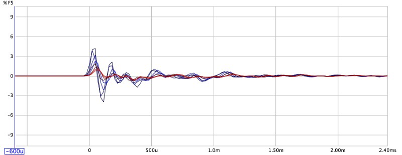
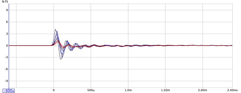
However, here's what the IRs look like overlaid:
An externally hosted image should be here but it was not working when we last tested it.
So I set the time window the same for all those graphs.
My bet is still on the cone break up being a part of the impulse that is causing the 2.5ms blip.
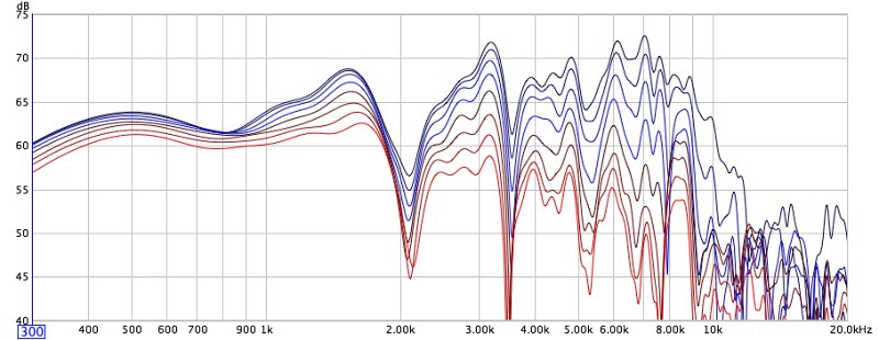
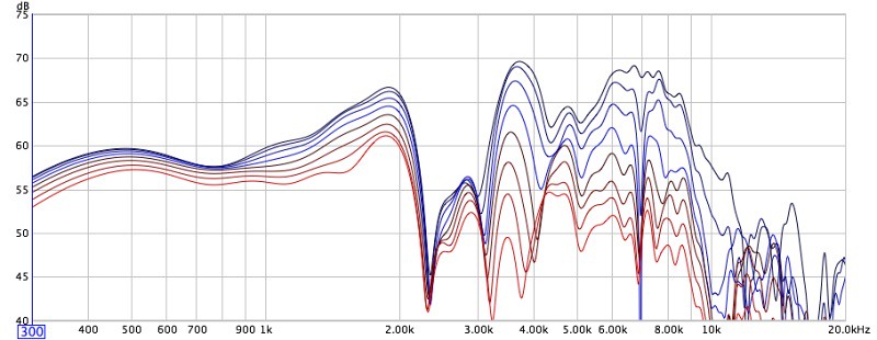
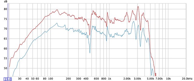
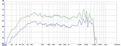
Look at this impulse responses from a driver where measuring conditions were identical and successive layers of damping compound applied:
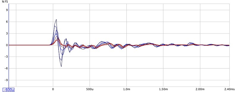
Corresponding polar graphs:
Dan
Last edited:
Where do I collect my money?
Pano -
I understand that some places in NC WILL accept this (see attached image) as legal tender. Just be aware that you might get paid in $3 bills

Attachments
Last edited:
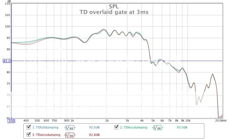
Thanks for the last graph. It's interesting how little effect the damping has on the frequency response, even from 2Khz and up..
Just a thought. Suppose the td15m would have been crossed at around 800Hz to the LeCleach horn, how much would the dip at 2.5Khz affect the sound quality?
I have little experience with crossover design and I'd like to know, in the eventuality of tackling a similar project, how many octaves of flat frequency should I aim around the crossover point.
Thank you!
- Home
- Loudspeakers
- Multi-Way
- Beyond the Ariel