TD15M has coating on its cone already. Further damping might probably add too much mass and affect other performances (in negative ways).
I agree -- I'm not going to do anything to the driver. It's my testing setup and methodology that need work.
Gary Dahl
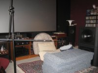
Following one Lynn's suggestions, I changed the mounting scheme for the test microphone. I mounted it on the end of a piece of plastic pipe (see photo), with the cable running through the center, so I wouldn't get an early reflection off the mic clamp. I also experimented with a whole bunch of Bonded Logic insulation batts (more than shown in the photo) and all the pillows in the house, in an effort to attenuate the floor bounce.
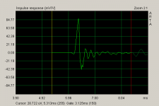
No matter what I tried, the impulse response showed a persistent wrinkle at 2.5 ms, which corresponds to a distance of just over 2.7 feet. Not sure where it's coming from. If I cut it off by setting the gate just before the wrinkle, all of those nasty ripples disappear from the frequency response graph. If I move the gate any later, the ripples are back. Ripples or not, the 1.5 kHz lift remains. I plan to use a crossover frequency of around 700 or 800 Hz, so it doesn't appear to be a terribly serious issue, but I do wonder why it's there.
I have attached a .zip archive containing both a .pir and a .wav file, in case you want to look at it on your own.
Gary Dahl
Attachments
There is really not much else you can do. Which is why lots of people will either use anechoic chamber or do outdoor measurements. The way Lynn mounts the mic is the best I've seen, and it does reduce reflections effectively viewed in CSD and impulse. You will probably not see much change in the SPL.
The best distance setup is using the speaker center and mic center as ellipitc focal points to draw and elliptical sphere, keep all objects out of that sphere.
The best distance setup is using the speaker center and mic center as ellipitc focal points to draw and elliptical sphere, keep all objects out of that sphere.
Last edited:
Gray, thanks for posting the IR files too.
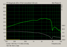
If I set the window before first reflections I get the on axis response below
Seems to be sort of "too good to be true" for a 15" (I could be wrong of course)")
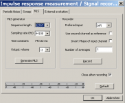
What were your settings for the IR measurement, actually and could you possibly try the settings I've shown for comparison?
Michael
If I set the window before first reflections I get the on axis response below
Seems to be sort of "too good to be true" for a 15" (I could be wrong of course)
What were your settings for the IR measurement, actually and could you possibly try the settings I've shown for comparison?
Michael
Attachments
Last edited:
If I set the window before first reflections I get the on axis response below...could you possibly try the settings I've shown for comparison?
Michael, with the same settings, I get the same on-axis response. But I don't think that snipping out that 2.5 ms wrinkle lets us see the whole picture, so I suspect it really is too good to be true.
John, it isn't the either of the sidewalls or the equipment rack on the left, which is too far away to be causing the 2.5 ms wrinkle. This morning I raised the speaker another 20" by adding the other TD15M cabinet to the stack. Now the center of the woofer is 50" off the floor, and there is a minimum of 50" of off-axis clearance in every direction. Microphone is at exactly one meter, and the 2.5 ms wrinkle is still there.
I think it would be interesting to build and install a grill frame (with no cloth at first) to see if filling the recessed area around the driver yields any improvement. Until I do, there is still that .25" edge all the way around. I'm not sure what to expect, though; the timing of the wrinkle doesn't seem to match up well with the distances involved.
With my current setup providing 50" of clearance all the way around, would measuring outside on the ground still be an improvement? How would I set that up -- vertically or horizontally?
Gary Dahl
Gary,
If your mic is at 39.4" and the closest reflecting surfaces are at 50" from the speaker, then the path length for a first reflection is about 107.5". So the path length difference is ~68.1" or 5ms after the direct sound, so that's probably not what you're seeing...
I'd say it's definitely worth going outside if you really want to see what's going on. You could take your same setup with the insulation on the ground and remove the effects of the wall and ceiling reflections in your room. Or you could put your mic on the ground, tip the cabinets forward a bit to point at the mic and lose the insulation to do a ground plane measurement. If the 2.5ms bump is still there in these cases (assuming any walls are further away), then you're seeing something from the enclosure or possibly mic stand although I find the mic stand less likely.
Member
Joined 2003
Reflection off the wall (CDs) behind the speaker?
Considered that, but it's more than 50" to the CD's, and 40" to the piano behind the speaker to the right, so it wouldn't explain that bugger at 2.5 ms.
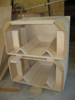
John, I think it may indeed be coming from the enclosure, although the actual cause is not readily apparent. There are two V-shaped diffusors on the back wall of the cabinet, one across the top, and a couple of small shelf braces on the sidewalls. I'll post a picture of the completed enclosure without the driver (gotta go to the other computer for that). The cabinet is filled with Bonded Logic, which is very highly absorptive.
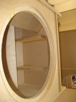
I'll see about setting up an outdoor measurement session, but I would first like to put in some grill frames so the front-panel diffraction will be at a minimum.
Thanks for all the help guys!
Gary Dahl
I'm putting my money on the panel diffraction.
We'll see. Here are some shots of the inside.
If it turns out to be those huge MDF corners that were so much work to build with, I'm gonna be ticked!

Attachments

I had the same mysterious 2ms reflections during my testing a few weeks ago. I was using HOLM and a Behringer mic. I was setup in the middle of an empty 25’ x 30’ room with a 13’ ceiling…and was well off the floor. Besides the speaker and mic, there was nothing in the room…nada. I, too, had tried remounting the mic, but got the same readings.
I wondering though…if it’s an enclosure problem, could it have been something coming through my passive radiators?
I wondering though…if it’s an enclosure problem, could it have been something coming through my passive radiators?
Well I guess the 2.3ms are a plain reflection form the back wall of the cabinet - this by the way could easily be traced down by a "Back Diaphragm Mirror Distortion" measurement (IM distortion).
What I do "miss" though are more pronounced peaks and dips up from roughly 1kHz due to cone break up (outdoor measurement is really not necessary to bring this up).
On the plots it looks as if there is massive smoothing involved in that department, though having the IR files published we could already check that its not been the case .
This leaves the measurement settings as "the usual suspects" - or - this 15" simply is an outstanding mid performer.
Michael
Last edited:
- this by the way could easily be traced down by a "Back Diaphragm Mirror Distortion" measurement (IM distortion).
Possibly even more easily for just a quick prove:
repeat the exact same measurement with and without dampening material in your box - and then post IR plots where we see the original peak and the reflection peak
The reflection peak should come alive seriously *if* I'm right
Michael
I listened to Gary's TD15M impulse response at very low spead (1/40 speed) and I think one can clearly identify a dampened back wall reflection. Following up there is a small amplitude but only slowly decaying train of brighter echoes until the first wall/floor reflections appear and the echo contours slowly disintegrate more and more into reverb.
In a perspective S-transform view the start of the IR looks like this, initial pulse ridge to left, the ridges of the first discrete reflections to the right (decreasing frequency along depth axis, X axis is 1ms/div, Y is 5dB/div), and the above mentioned low level echoes might be identified in the pretty repetitve pattern in between.
Klaus
Attachments
Last edited:
It's been a busy day.
I built a set of grill frames and installed one on the TD15M cabinet. Everything's all flush now. No noticeable difference in measurements.
Next, I removed the damping from the back wall and ceiling of the cabinet. These are the .pir and .wav files named "lessdamping."
Afterward, I replaced the previously-removed damping, and added a second layer between the driver and the back of the cabinet. This resulted in the box being completely filled, except of course for the area inside the driver basket. These are the .pir and .wav files named "fulldamping."
Finally, I completely removed all of the damping material from the cabinet. These are the .pir and .wav files named "zerodamping."
That blip at 2.15 ms still looks the same to me.
The Bonded Logic material has excellent sound blocking properties. A single layer of R-13 (3.5" thickness) has an STC rating of:
21 at 125 Hz
40 at 250 Hz
48 at 500 Hz
52 at 1 kHz
46 at 2 kHz
48 at 4 kHz
If the 2.5 ms wrinkle was caused by a reflection inside the cabinet, I would think that the difference between an empty cabinet and one full of damping material would be obvious. But that wrinkle is still there!
Looks like I'm gonna have to take this fight outside.
Gary Dahl
Attachments
Last edited:
- Home
- Loudspeakers
- Multi-Way
- Beyond the Ariel