all exposed conductive parts must be connected to Safety Earth.What will be the differences compared to a resistor or just nothing? Or even a plain wire?
Do not use "just nothing" nor use a "resistor" alone.
This connection MUST be able to pass thousands of amperes and survive long enough for the mains fuse to rupture and the arc to extinguish.
It Must be:
a direct wire link,
or
a pair of high power inverse parallel diodes,
or
a high power Thermistor.
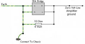
Sorry for being unclear. I was meant to state (or ask?) that the CL-60 behaves similar to a ground breaker without the capacitor. See the attached schematic.
When there's no voltage present, both will act as a 10ohm resistor tying chassis and ground. When voltage increases, it becomes a closed circuit
.
In the case of the ground breaker, it will close the circuit when there is a voltage over 1.5-2v (the diode voltage drop). When applied that voltage, the diodes conduct thus bridging the resistor, giving a result of 0 ohms.
In the case of the CL-60, as soon as voltage starts to increase, resistance decreases until it reaches (theorically) 0 ohms. We would need to know the graph curve to see how effective it is.
With a diode bridge breaker, it suddenly changes from 10 ohms to 0 ohms as soon as it reaches those ~2v.
I hope now it is clearer")
Regards,
Regi
When there's no voltage present, both will act as a 10ohm resistor tying chassis and ground. When voltage increases, it becomes a closed circuit
.
In the case of the ground breaker, it will close the circuit when there is a voltage over 1.5-2v (the diode voltage drop). When applied that voltage, the diodes conduct thus bridging the resistor, giving a result of 0 ohms.
In the case of the CL-60, as soon as voltage starts to increase, resistance decreases until it reaches (theorically) 0 ohms. We would need to know the graph curve to see how effective it is.
With a diode bridge breaker, it suddenly changes from 10 ohms to 0 ohms as soon as it reaches those ~2v.
I hope now it is clearer
Regards,
Regi
Attachments
And what about the outputs binding posts? it is an exposed conductive part.all exposed conductive parts must be connected to Safety Earth.
Do not use "just nothing" nor use a "resistor" alone.
if the conductive parts are exposed then they must be connected to Safety Earth. That's why the shrouded speaker terminals came about. But they are very unpopular.And what about the outputs binding posts? it is an exposed conductive part.
Similarly the input RCA barrel is exposed as soon as the interconnect is removed.
The RCA hot input is exposed at the remote end of the interconnect, if it is left unconnected. That's the really dangerous one if youngsters are still sucking on anything they investigate.
I do wish ESP would re-draw that post322 diagram.
It should show the Protective Earth wire (third wire in the mains cable) directly and permanently connected to conductive chassis.
The Disconnecting Network will connect from any other part of the conductive chassis to the Main Audio Ground. It does not have to coincide with the PE connection. I believe the "permanent" requirement implies that these two connections to chassis should not coincide.
Last edited:
In fact, this one is the re-drawn one by me. This is the original one:I do wish ESP would re-draw that post322 diagram.
http://sound.westhost.com/earth-f4.gif
This thread was started for the Mauro My Ref Rev_C so I will try to stay on topic.
The amp was designed with a floating pwr supply. That's how I use it and have no issues.
However, the PGND connection between the two pwr supply caps can be tied to the chassis if desired.
I (personal opinion) would NOT use a direct link or straight wire.
I (personal opinion) would use a CL-60 and may just try that to see if it has an affect.
I (personal opinion) don't think there would be anything wrong with the Rodd Elliot diagram for the DC blocker circuit but a single CL-60 is simpler.
most regulations do not give you this choice.The amp was designed with a floating pwr supply. That's how I use it and have no issues.
However, the PGND connection between the two pwr supply caps can be tied to the chassis if desired
"A floating pwr supply" and exposed conductive parts is quite simply not allowed.
If there are any exposed conductive parts then one MUST connect them to Safety Earth, irrespective of how the amplifier was designed or intended to be used.
most regulations do not give you this choice.
"A floating pwr supply" and exposed conductive parts is quite simply not allowed.
If there are any exposed conductive parts then one MUST connect them to Safety Earth, irrespective of how the amplifier was designed or intended to be used.
In DIY one can CHOOSE to do whatever he / she desires.
There are no rules, but hopefully common sense.
I recommend professional training / education / mentoring or a whole lot of questions to the forum and patience waiting for answers back.
Well, it's time to give some preliminary results about my tests:
C5 (diodes filtering):
No cap is a very important improvement, I'll try some 10nF MKP10 (Lead spacing 7.5mm, prefect fit). (D2 and D3 must be soft recovery diodes!!)
C7 (LM318 bypass):
In C7 I've tried Evox SMR5, Wima MKS2 and MKP2 in 220nf and 100nF values, 10nF FKP2 too;
MKP2 (included in kit) is a very nice upgrade versus the MKS2 but compared to SMRs and FKP2s is closed.
SMRs have gorgeous high and medium range but lacks some bass, FKP2 a bit less gorgeous but much more equilibrated.
Best of all is no C7 cap at all but stability could be a concern...
C6, C11 (Zeners bypass)
Tried Wima 4.7uF MKS2XL in place of the Silmics, it seems a nice upgrade but at 2x the cost. Waiting them burning in...
C10 filtering
Tried a Silver Mica and there's a subtle improvement, a bit more refined high range.
C12 filtering
A FKP2 here make a big difference: RECOMENDED and DEFINITIVE!
C34 LM318 compensation
Tried a Silver Mica and there's a not so subtle but neither so big effect, more refined high range and tighter bass.
R13 input shunt resistor
Tried a single swap between PRPs and Caddocks MK132, after that one of the legs broke (@#!)
There's a nice but subtle improvement: a bit more refined high range, more body and harmonics.
If cost is no object the Caddock is the clear winner but a cost conscious build probably would drop it for a Takman Carbon Film.
R3 output resistor
Tried the standard Xicon of the previous GB, the Caddock MP915 and a Mills MRA-5.
The Caddock is better than the Xicon, more refined and open but difference is not so big for 6x the cost...
The Mills is strange, is the more refined of all three but is somewhat dinamically challenged... and directional (!)
If cost is no object the Caddock is the winner but a cost conscious build probably would drop it...
LM318
Mounted and burning in the metal can version, it seems a nice but a bit subtle upgrade.
Disclaimer: All those test could change results with burn-in of components and further listening sessions.
The unique exception is the 220pF FKP2 in C12, IMHO a definitive and suggested mod.
Exactly...
Removing C5 gives a better sound but you can remove it only if also D2 and D3 are soft recovery diodes and not the stock 1N4001.
C5 is there to remove diodes spikes...
But a 10nF MKP10 could do the 100nf MKP4 job better, I've had a report about 100 nF MKP10 sounding better in that position.
Removing C5 gives a better sound but you can remove it only if also D2 and D3 are soft recovery diodes and not the stock 1N4001.
C5 is there to remove diodes spikes...
But a 10nF MKP10 could do the 100nf MKP4 job better, I've had a report about 100 nF MKP10 sounding better in that position.
Thanks for your feedback, Dario. These are very interesting experiments.
You're welcome Regi
Some more data to crunch...
My friend (see this post) wrote me to suggest the removal of C21 with the Black Gate in C9.
He found that bypassing C9 creates some sort of resonance on the very high range and in some way it messes up phase coherency.
It seems that the general consesus on not to bypass BGs gained one more vote...
Currently I'm using the MP915 Caddocks without heatsinks and they're only slightly warm (my Loudspeakers have a 90dB efficency)...
How they're going in yours setups?
7Apk is the guaranteed minimum output current of a cold 3886.
-20dB average playing is just 0.7pk or ~0.5Arms.
The half ohm Caddock will dissipate ~125mW when playing a -20dB average signal..
Even playing louder transients at -10dB ref maximum output current will only increase the Caddock dissipation to ~1.3W.
We all know that transients, by definition, do not cause excessive heating of the output resistor.
If your half ohm Caddock gets warm you are misusing your MyRefC.
From the Caddock datasheet: Without a heat sink,
when in free air at +25°C, the MP915 is rated for 1.25
watts
These conditions will drive the resistor temperature up to 150C. The thermal resistance with no heatsink is 100C/W.
It is agreed that playing music at sane levels should not cause the resistor to get extremely hot. Keep in mind that the resistor element will be 10C hotter than the case at 1.25W dissipation.
Transients are generally rated by the manufacturer as single non-repetitive events which may or may not correlate well with particular types of music. Transients having a pulse width less than 100msec should not be troublesome. See Caddock's application note AEN0101 for more information.
For me it is a requirement that the amplifier be capable of putting out full power sine waves continuously on the test bench. A heatsink is definitely needed for that and since it is supplied, I recommend that it be used.
A heatsink is definitely needed for that and since it is supplied, I recommend that it be used.
Hi Bill,
obviously I wasn't suggesting to use them without heatsink.
But for sure I'll search a smaller one.
- Status
- This old topic is closed. If you want to reopen this topic, contact a moderator using the "Report Post" button.
- Home
- Amplifiers
- Chip Amps
- MyRefC build guide