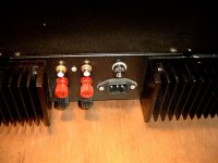
The line input cannot be placed so close from the speakers output and power supply input")
There was not that much room left at the back to space them wider apart. So I agree with you, but I didn't do it.
Attachments
I see. In this case, variants are not presentThere was not that much room left at the back to space them wider apart. So I agree with you, but I didn't do it.
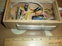
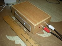
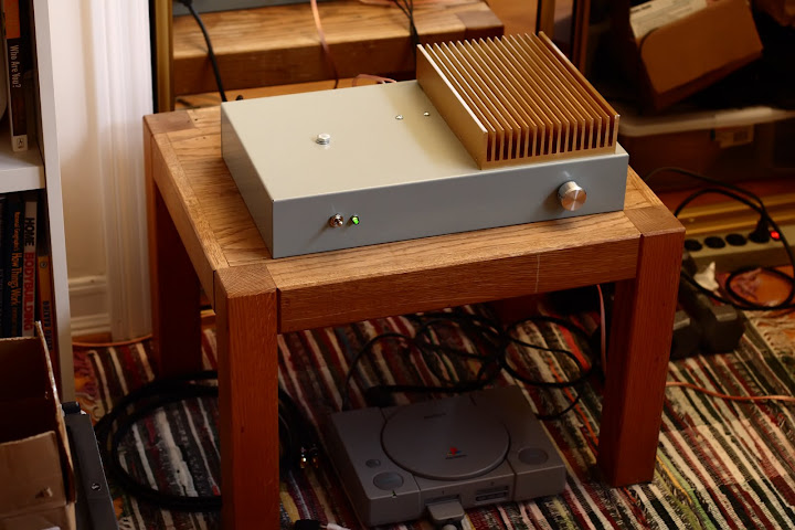
Mini LM1875 based desktop amp
Just finished! A headphone jack may be added is the only thing:
Full details and more pics in the build thread:
http://www.diyaudio.com/forums/chip-amps/168553-lm1875-miniature-desktop-amplifier-build.html
Ted, I like that, how the heatsink extends out of the wooden box. That seems like quite a nice performing chip too actually
Just finished! A headphone jack may be added is the only thing:
An externally hosted image should be here but it was not working when we last tested it.
An externally hosted image should be here but it was not working when we last tested it.
Full details and more pics in the build thread:
http://www.diyaudio.com/forums/chip-amps/168553-lm1875-miniature-desktop-amplifier-build.html
Ted, I like that, how the heatsink extends out of the wooden box. That seems like quite a nice performing chip too actually

Hi,
I guess I'm rather late to the Party, at least with build pictures.
You could say the first ever Amp I build was a chipamp too, very long ago (some time in the early to mid 70's IIRC). It was based on the east german copy of the TBA810AS Chip (A205K), but it had discrete single transistor preamp for tone control and of course obligatory loudness volume control. Of course, this was build all proper on a Circuit board, hand drawn and eteched in iron cloride or whatever this nasty stuff is and then drilled by hand.
Working with some 8" full range drivers taken from old tube TV's and using a portable FM Radio (fitted DIY with a Stereo Decoder) as source this sounded quite nice, to my very, very young self.
I build quite a few Amplifiers with Chips later, long before the "Chipamp" became a household name. In the early days of gaincloning I had my fingers in the pie too and I still am occasionally attributed the "inverting gainclone" (Hardly my design, anyone can use a chipamp inverting, it's right there in Horrowitz & Hill).
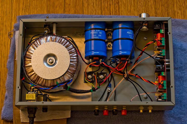
A few years back I needed a temporary but Decent Amp so I build a Gainclone in the case an old old blown up up amplifier, namely an Audio Innovation Alto:
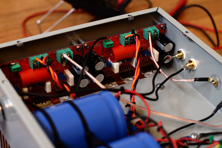
The Insides look a little more chaotic, practically everything is hardwired:
The transformer inside was perfect for a gainclone, so it stayed.
The Powersupply combines a little of everything, or should I just say my own take. I used MUR860 (On-Semi) mainly because I had them around, I normally prefer schottky diodes.
The PSU Capacitors are 3,300uF/50V Elna Silmic II. The first pair is directly after the rectifiers, unbypassed. Each of the three lines (+V, -V and gnd) then connect via a pair of parallel 0.47 Ohm resistors to the second pair of capaictors, which are bypassed and snubbered (ThanX Carlos).
PSU Wiring is 1mm solid silver in PE Tubing pulled from my favourite RF Coaxial Cable, three strands per connection carrying +/-/gnd. Star wired to each Amp section and to the speaker binding posts.
For a number of reasons this Amp is non-inverted, bog standard App Note Circuit, but with local Elna Silmic II PSU Cap's (100uF/50V IIRC) and AB Carbon Composite Resistors (handselected for perfect channel match).
Frontend is a genuine Alps Blue motorised pot (not china fakes) with the silcone chip remote control kit. I could have used a Noble Pot but that would have meant no remote control, I am getting lazy in my old age.
Relay based input switching (forgot whose' relays, some nice ones), signal wiring is silver, 1mm for grounds and 0.2mm for each signal, again using these salvaged coax cables, here the shield was left in place.
That's it.
The Amp sounds quite okay, it beat the stuffing out of a Naim Nait and several other pretty expensive SS Amp's, it readily looses against any of my Tube Amp's though. Currently it gathers dust, so I'll probably break this apart some time soon to put something else inside.
Ciao T
PS, yes, I have the matching CD-Player...
I guess I'm rather late to the Party, at least with build pictures.
You could say the first ever Amp I build was a chipamp too, very long ago (some time in the early to mid 70's IIRC). It was based on the east german copy of the TBA810AS Chip (A205K), but it had discrete single transistor preamp for tone control and of course obligatory loudness volume control. Of course, this was build all proper on a Circuit board, hand drawn and eteched in iron cloride or whatever this nasty stuff is and then drilled by hand.
Working with some 8" full range drivers taken from old tube TV's and using a portable FM Radio (fitted DIY with a Stereo Decoder) as source this sounded quite nice, to my very, very young self.
I build quite a few Amplifiers with Chips later, long before the "Chipamp" became a household name. In the early days of gaincloning I had my fingers in the pie too and I still am occasionally attributed the "inverting gainclone" (Hardly my design, anyone can use a chipamp inverting, it's right there in Horrowitz & Hill).
A few years back I needed a temporary but Decent Amp so I build a Gainclone in the case an old old blown up up amplifier, namely an Audio Innovation Alto:
An externally hosted image should be here but it was not working when we last tested it.
The Insides look a little more chaotic, practically everything is hardwired:
An externally hosted image should be here but it was not working when we last tested it.
The transformer inside was perfect for a gainclone, so it stayed.
The Powersupply combines a little of everything, or should I just say my own take. I used MUR860 (On-Semi) mainly because I had them around, I normally prefer schottky diodes.
An externally hosted image should be here but it was not working when we last tested it.
The PSU Capacitors are 3,300uF/50V Elna Silmic II. The first pair is directly after the rectifiers, unbypassed. Each of the three lines (+V, -V and gnd) then connect via a pair of parallel 0.47 Ohm resistors to the second pair of capaictors, which are bypassed and snubbered (ThanX Carlos).
PSU Wiring is 1mm solid silver in PE Tubing pulled from my favourite RF Coaxial Cable, three strands per connection carrying +/-/gnd. Star wired to each Amp section and to the speaker binding posts.
For a number of reasons this Amp is non-inverted, bog standard App Note Circuit, but with local Elna Silmic II PSU Cap's (100uF/50V IIRC) and AB Carbon Composite Resistors (handselected for perfect channel match).
An externally hosted image should be here but it was not working when we last tested it.
Frontend is a genuine Alps Blue motorised pot (not china fakes) with the silcone chip remote control kit. I could have used a Noble Pot but that would have meant no remote control, I am getting lazy in my old age.
Relay based input switching (forgot whose' relays, some nice ones), signal wiring is silver, 1mm for grounds and 0.2mm for each signal, again using these salvaged coax cables, here the shield was left in place.
That's it.
The Amp sounds quite okay, it beat the stuffing out of a Naim Nait and several other pretty expensive SS Amp's, it readily looses against any of my Tube Amp's though. Currently it gathers dust, so I'll probably break this apart some time soon to put something else inside.
Ciao T
PS, yes, I have the matching CD-Player...
PS, yes, I have the matching CD-Player...
I have the CD player with the Audio Partnership boards inside. Got it broken for £20. I think it sounds great. What is your opinion? I have tried to see what Dac it uses. Do you know?
Hi,
The CD sounds okay to my ears, after quite a few modifications.
The DAC is CS4327, the last decent sounding DAC Cirrus Logic ever made, basically a budget version of the CS4328 which was justly famous in it's day.
The PCB's are basically the same as one particluar Cambridge Audio CDP.
It was designed by John Westlake of triangle fame (who occasionally posts here).
My mods where mainly "Os-Con plus SMD Ceramics everywhere"; I upgraded the Op-Amp's (AD8620 for output I remember, one other which regulates the reference voltage where I used a nice fast low noise one, can't remember which).
BTW, neither Amp nor CD are used in my main system anymore, in fact both collect dust.
Here is what is playing right now:
Audio Asylum - Inmate Systems
Ciao T
I have the CD player with the Audio Partnership boards inside. Got it broken for £20. I think it sounds great. What is your opinion? I have tried to see what Dac it uses. Do you know?
The CD sounds okay to my ears, after quite a few modifications.
The DAC is CS4327, the last decent sounding DAC Cirrus Logic ever made, basically a budget version of the CS4328 which was justly famous in it's day.
The PCB's are basically the same as one particluar Cambridge Audio CDP.
It was designed by John Westlake of triangle fame (who occasionally posts here).
My mods where mainly "Os-Con plus SMD Ceramics everywhere"; I upgraded the Op-Amp's (AD8620 for output I remember, one other which regulates the reference voltage where I used a nice fast low noise one, can't remember which).
BTW, neither Amp nor CD are used in my main system anymore, in fact both collect dust.
Here is what is playing right now:
Audio Asylum - Inmate Systems
Ciao T
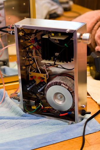
my first lm3886 gainclone circa 2008
My first gainclone attempt. Great sounding amp implemented by an amateur audio / electronics enthusiast. 250VA toroid, two lm3886s, and one overly ridiculous star ground haha. I'm in the process of building a new amp, it's been nearly two years since this photo was taken when I built this amp.
My first gainclone attempt. Great sounding amp implemented by an amateur audio / electronics enthusiast. 250VA toroid, two lm3886s, and one overly ridiculous star ground haha. I'm in the process of building a new amp, it's been nearly two years since this photo was taken when I built this amp.
I have just finished.
LM3886 Gainclone with PGA2311 stepped attenuator.
LM3886 Gainclone with PGA2311 stepped attenuator.
An externally hosted image should be here but it was not working when we last tested it.
An externally hosted image should be here but it was not working when we last tested it.
An externally hosted image should be here but it was not working when we last tested it.
Hey guys
Heres my 90% finished my Gainclone
its Based on the Audiosector Classic LM3875 kit built as an integated amp 300va 2x25v
The chassis was a scratch build from aluminium with a temp Corian front panel till i get a 10mm aluminium plate CNC machined.
The 48mm Volume knob was souced on Ebay from seller 8audio based in china but delivery was quick .
I wrote a quick and dirty guide below for bending aluminium if anyones interested in making their own chassis
http://bit.ly/d7ayVE
Rupert
An externally hosted image should be here but it was not working when we last tested it.
An externally hosted image should be here but it was not working when we last tested it.
An externally hosted image should be here but it was not working when we last tested it.
An externally hosted image should be here but it was not working when we last tested it.
An externally hosted image should be here but it was not working when we last tested it.
An externally hosted image should be here but it was not working when we last tested it.
Folks,
I think this one also qualifies as Gainclone, if only in the loosest possible sense...
Upfront, this will be a commercially available Kit/Finished item from diyhifisupply, however I think it may still give some ideas to some here, so I think it is worth posting up as well...
The whole project is as follows:
Small diyhifisupply project enclosure package fitted with:
192KHz/24 Bit Asyncronous USB DAC
Input Selection/Volume Control
Tube Amplification Stage
Nat Semi Chip based powerstages
Powersupply based around a custom 260VA Torroid Transformer with suitable windings to power the rest
Measured output power is around 45/65W into 8/4Ohm at clipping.
It looks like this (the picture includes the PC that stores the music and the TV that acts as monitor for this PC):
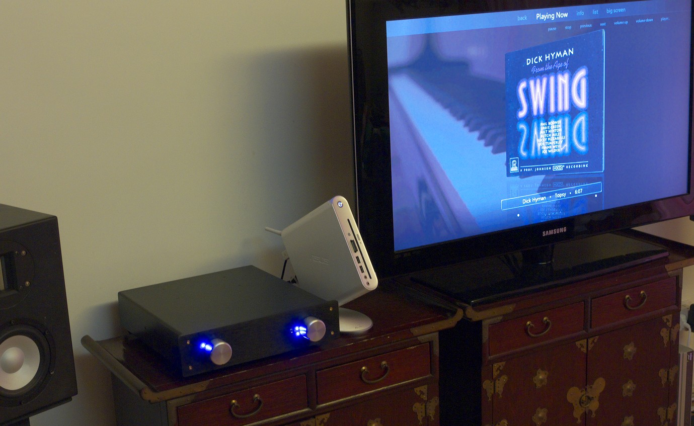
Not the most inspring casework (for one it's black), but solid and professional looking.
The insides at some point in time during the build, prior to wiring everything up (it now looks a little messier, but not hugely):
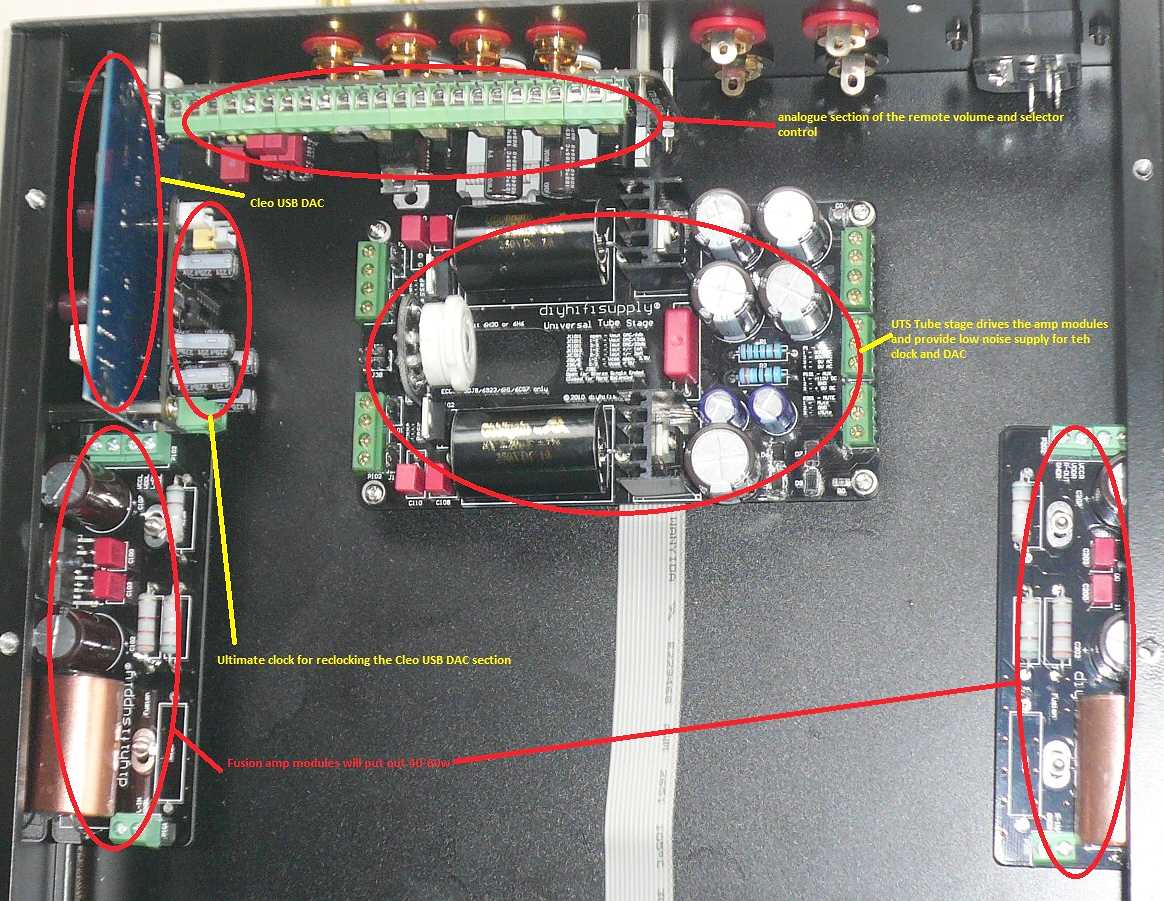
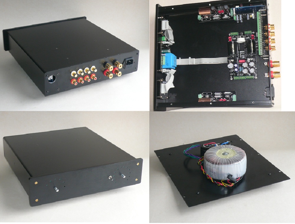
Here another set of piccies showing how it fits together:
diyAudio
All the signal circuitry is build into the Project case extruded Alu shell, the power supply is bolted to the case bottom plate, which closes up the case.
This whole thing was wired with 1mm solid silver in PTFE tubing for speaker connection, 0.5mm solid silver for the grounds and 0.25mm solid silver for the signals, power supplies are wired with coloured stranded copper.
The modules used in turn...
The DAC is basically a heavily modified Musiland Monitor 01 US. It is powered from a the Powersupply module that accompanies the clock module fitted (it has enough spare capacity). Outputs were taken from the positive voltage outputs straight into a pair of 0.22uF Teflon coupling caps.
Next is a Input selector/volume controlmodule based around DS-1666 100KOhm "stepped attenuator on a chip".
The output from that feeds the Universal Tube Stage (here with full 30dB Gain).
This in turn drives a modified "Fusion" Module. The original Fusion Module is intended as "afterburner" for SET Amplifiers (it is essentially a current multiplier). It is based around one of the "usual suspects" Nat Semi chips.
Here the Fusion module is modified to give some gain (around 3 - yes, I know, Nat Semi LM38XX Chips are not stable at gains of less then 10, well they are unless you are me, there are some circuit tricks that overcome this limitation) and the actual "Fusion" circuit is disabled, as the small signal tube stage lacks the necessary power to make this work.
The result is actually a lot better than I expected and a lot better than it should.
Dropped into the office system instead of a standalone Tubes USB DAC implementation of the same Musiland Monitor PCB, the Tram II DHT Linestage and a pair of our Lux 91 Monoblocks without any playtime the results were surprising musical and this little single box solution was by no means outclassed, even though the DHT Line Stage, 300B Amps and so on retained a bit of a lead. But TBH, I could live with this box, if I had to...
I'm going to build another one for my own office as soon as I get the time.
The rest of the story (for background, the PC side of things and other stuff) you can find here:
http://www.diyaudio.com/forums/diy-hifi-supply/168301-fi-flora.html
Ciao T
I think this one also qualifies as Gainclone, if only in the loosest possible sense...
Upfront, this will be a commercially available Kit/Finished item from diyhifisupply, however I think it may still give some ideas to some here, so I think it is worth posting up as well...
The whole project is as follows:
Small diyhifisupply project enclosure package fitted with:
192KHz/24 Bit Asyncronous USB DAC
Input Selection/Volume Control
Tube Amplification Stage
Nat Semi Chip based powerstages
Powersupply based around a custom 260VA Torroid Transformer with suitable windings to power the rest
Measured output power is around 45/65W into 8/4Ohm at clipping.
It looks like this (the picture includes the PC that stores the music and the TV that acts as monitor for this PC):
Not the most inspring casework (for one it's black), but solid and professional looking.
The insides at some point in time during the build, prior to wiring everything up (it now looks a little messier, but not hugely):
Here another set of piccies showing how it fits together:
diyAudio
All the signal circuitry is build into the Project case extruded Alu shell, the power supply is bolted to the case bottom plate, which closes up the case.
This whole thing was wired with 1mm solid silver in PTFE tubing for speaker connection, 0.5mm solid silver for the grounds and 0.25mm solid silver for the signals, power supplies are wired with coloured stranded copper.
The modules used in turn...
The DAC is basically a heavily modified Musiland Monitor 01 US. It is powered from a the Powersupply module that accompanies the clock module fitted (it has enough spare capacity). Outputs were taken from the positive voltage outputs straight into a pair of 0.22uF Teflon coupling caps.
Next is a Input selector/volume controlmodule based around DS-1666 100KOhm "stepped attenuator on a chip".
The output from that feeds the Universal Tube Stage (here with full 30dB Gain).
This in turn drives a modified "Fusion" Module. The original Fusion Module is intended as "afterburner" for SET Amplifiers (it is essentially a current multiplier). It is based around one of the "usual suspects" Nat Semi chips.
Here the Fusion module is modified to give some gain (around 3 - yes, I know, Nat Semi LM38XX Chips are not stable at gains of less then 10, well they are unless you are me, there are some circuit tricks that overcome this limitation) and the actual "Fusion" circuit is disabled, as the small signal tube stage lacks the necessary power to make this work.
The result is actually a lot better than I expected and a lot better than it should.
Dropped into the office system instead of a standalone Tubes USB DAC implementation of the same Musiland Monitor PCB, the Tram II DHT Linestage and a pair of our Lux 91 Monoblocks without any playtime the results were surprising musical and this little single box solution was by no means outclassed, even though the DHT Line Stage, 300B Amps and so on retained a bit of a lead. But TBH, I could live with this box, if I had to...
I'm going to build another one for my own office as soon as I get the time.
The rest of the story (for background, the PC side of things and other stuff) you can find here:
http://www.diyaudio.com/forums/diy-hifi-supply/168301-fi-flora.html
Ciao T
Last edited:
gainclone 2
My second gainclone, based on some paralell 150w lm3886 boards i found on ebay, this thing rocks! Unlike my last amp, there is absolutely zero noise at the speaker terminals at any volume setting, and the chips stay very cool with the massive heatsink... Overall a great sucess
My second gainclone, based on some paralell 150w lm3886 boards i found on ebay, this thing rocks! Unlike my last amp, there is absolutely zero noise at the speaker terminals at any volume setting, and the chips stay very cool with the massive heatsink... Overall a great sucess
AWSEOME
Funny enough i am busy with VERY much the same amp:
I designed my own enclosure for the heatsinks i bought. received the enclosure yesterday so busy assembling everything now.
In the end it is going to be stereo or switeable to bridge mode. Very much the same as the bpa300.
Funny enough i am busy with VERY much the same amp:
I designed my own enclosure for the heatsinks i bought. received the enclosure yesterday so busy assembling everything now.
An externally hosted image should be here but it was not working when we last tested it.
An externally hosted image should be here but it was not working when we last tested it.
An externally hosted image should be here but it was not working when we last tested it.
In the end it is going to be stereo or switeable to bridge mode. Very much the same as the bpa300.
Hi,
It is called lag/lead compensation and has been covered before.
Sorry, I will not publish any schematics or values for this, no need to make it too easy for copy-cats. The answers are in Horowitz & Hill.
Ciao T
ThorstenL, could you explain how did you managed to make an LM3886 stable with a gain lower than 10?
You can get almost any circuit stable with gains below 10, if you know where and how to compensate. Doesn't say that it does sound better/good
With kind regards,
Bas
- Home
- Amplifiers
- Chip Amps
- Chip Amp Photo Gallery