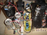
Looks cleaner now. Depends. Me with AC heating everywhere and no choke plus a 250VA toroid smack in the heart of the assembly I am like the pic, and its silent on 95dB speakers. You should achieve better in the end with your chokes, double mono etc. I guess.
Attachments
Had a very enjoyable time on Holiday (where it was warm) and have now had the time to recoup enough to get this project moving again. First thing I did was spend some time on my measurement system by finishing pmillet's soundcard interface. It has made a significant difference in repeatablity and reducing noise pick-up. Am VERY pleased to have that in my diy system.
I am now up to version 14 of the amp schematics. Based on some of the prior comments and suggestions from Salas and others, I have arrived to a point were I feel it is time to get it into the chassis. The biggest change was dropping the input tube bias current from 8mA to 4mA. Noise floor dropped almost 10dB and THD is <0.01% at 1W. I still have some power supply fundementals to deal with, however, I have concluded that much of that issue is related to my test cell that I built.
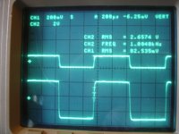
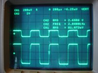
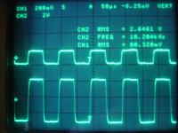
I think there is plenty of room for improvement but this isn't half bad for right now. As you will see in the following scope pics of square wave, the tilt has for the most part been eliminated. I have posted 1kHz, 2kHz, and 10kHz. The top trace is the input signal and the lower is the output across a 5R dummy load. Gain is 30dB.
I am now up to version 14 of the amp schematics. Based on some of the prior comments and suggestions from Salas and others, I have arrived to a point were I feel it is time to get it into the chassis. The biggest change was dropping the input tube bias current from 8mA to 4mA. Noise floor dropped almost 10dB and THD is <0.01% at 1W. I still have some power supply fundementals to deal with, however, I have concluded that much of that issue is related to my test cell that I built.
I think there is plenty of room for improvement but this isn't half bad for right now. As you will see in the following scope pics of square wave, the tilt has for the most part been eliminated. I have posted 1kHz, 2kHz, and 10kHz. The top trace is the input signal and the lower is the output across a 5R dummy load. Gain is 30dB.
Attachments
Last edited:
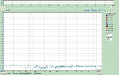
In this post I have some measurements.
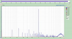
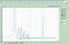
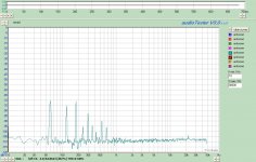
First is the amp powered on with no signal. The input is not grounded, just with signal off. As you can see I have alot of power supply noise to work out of the spectrum. Again I feel this is related to my test bench. I can change it by moving wires etc. I can't hear it on my speakers but I am sure if it was on more efficient ones it would be audible.
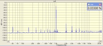
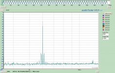
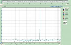
The second is a 1 kHz signal. THD is <0.01%% at 1 watt.
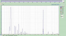
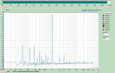
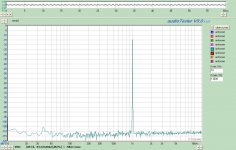
The third is IMD 70Hz/6kHz with the fourth being an expanded scale around 6kHz. IMD is around 0.005%
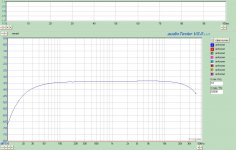
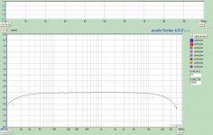
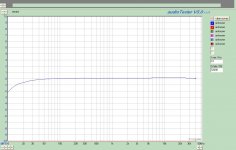
Finally the freq response into 5R. I am a little concerned about the HF roll off.
First is the amp powered on with no signal. The input is not grounded, just with signal off. As you can see I have alot of power supply noise to work out of the spectrum. Again I feel this is related to my test bench. I can change it by moving wires etc. I can't hear it on my speakers but I am sure if it was on more efficient ones it would be audible.
The second is a 1 kHz signal. THD is <0.01%% at 1 watt.
The third is IMD 70Hz/6kHz with the fourth being an expanded scale around 6kHz. IMD is around 0.005%
Finally the freq response into 5R. I am a little concerned about the HF roll off.
Attachments
Last edited:
A cleaner image of what it does. The Mosfet buffers, & current source loads/drains must be key to your fine THD & IMD results. If you just loop the FFT system on itself including the new interface, what is its residual noise floor? The harmonic noise isn't good if it is the amp mainly. Must be addressed in such a case. The left and right extension looks like some more NFB is needed. To the left is more problematic than to the right. Are the interstage couplings big enough? Does it contract further in more power? The square tests don't indicate such LF roll off, check your measurement set up's frequency response in self loop too.
Okay here is the loopback test. 1kHz 2.63V signal, No signal, and 0.8V signal.
When you discuss to the left I am assuming the harmonics < 1kHz. That is (at least what I believe) to be my power supply test set-up. I am embarrased to admit it but the test cell for the amp plate is a mess and has wires everywhere. I can significantly improve the spectrum by carefully moving the wires around.
Yes, the amp could probably use more NFB. That is easy enough to do even in the chassis. My first step is to clean up the PS noise. I then want to optimize the NFB.
Attachments
Great. Now we know its not your FFT set up. Its crucial we don't have wrong assumptions. To the left I did not mean the harmonic noise. That you will be able to reduce more and more by proper final assembly and correct wiring to avoid loops and magnetic fields I hope. It may very well be a ground loop in the amp itself, not the experimental PSU assembly. But having the FFT capability you will be able to see what helps or not. You are not blind with it. I was talking the LF roll off. If you measure your loop FFT frequency response, is it extending more? Because your square waves look good for not a leaning enough top.
Yes it is much clearer now.
Here are three plots
First the loopback with a calibration file.
Second Amp under test. 1 W. With the input cap
Third Amp under test without the input cap.
The input cap was not for DC but to control large LF error signals with NFB.
Here are three plots
First the loopback with a calibration file.
Second Amp under test. 1 W. With the input cap
Third Amp under test without the input cap.
The input cap was not for DC but to control large LF error signals with NFB.
Attachments


We are fellow hobbyists, comes naturally. Did you spot an interesting difference between our two amps? Weaker drive and more capacitive trioded output stage in conjunction with same 12AT7 splitter, in mine produce 2nd harmonic dominant but 3rd in yours. Yours by the book, mine by the cook.
Don't know, maybe losing an anode CCS to a resistor can change the order a bit, you got very low THD already maybe you can afford some increase if it happens. The main thing is UL that puts a stamp. Such things you have to evaluate subjectively in stereo later I guess. Just leave space to have a good hand for changes. In general a PP amp has more 3rd, its natural.
I think that for right now I will leave it alone. Plenty of room for play in the future.
I am in a quandary right now. My right side is itching to get this channel in the chassis and fire up the second one, while my left side doesn't want to stop listening to it as it is for the night....
I am in a quandary right now. My right side is itching to get this channel in the chassis and fire up the second one, while my left side doesn't want to stop listening to it as it is for the night....
The second Channel in the Chassis
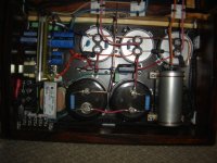
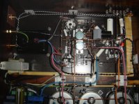
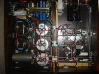
Been a while, but time for an update and some peer review.
Have now fired up the second channel and put it into the chassis. I won't post measurements yet as I had a shorted GES kt88 and don't have the correct value for feedback caps. So it is running with a little ring in the square wave on my EH kt88's. They are on order so maybe by next week I can get that completed. In general the PS noise is down 25dB with a couple of peaks at 60 and 120Hz. The harmonic spectrum below 1kHz is much cleaner. THD as it stands now measures at 0.028% 1kHz 1W. A little higher than my other channel. The GEC measured lower but I didn't save the measurement so can't recall correctly.
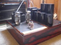
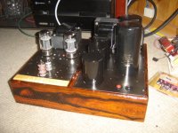
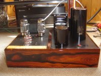
Here are the photo's of the amp. Both inside and out. I am really interested in your comments on what is right and what is wrong with the construction. Any and all comments, criticisms etc are welcome. I plan to redo the amp plate at some point in the near future to move the kt88's away from the OPT as well as try to pull the FETS off of the plate to reduce parasitic capacitance.
Thanks for your help so far in making this thing a reality.
Oh yea, it does sound really good. Very dynamic, detailed with and with an incredible and stable soundstage. It is way too early yet to give it any more critical feedback. Since I built it, listening fatigue may take a while to set in if it is going to and I wouldn't want to lead anyone astray on its qualities or faults.
Been a while, but time for an update and some peer review.
Have now fired up the second channel and put it into the chassis. I won't post measurements yet as I had a shorted GES kt88 and don't have the correct value for feedback caps. So it is running with a little ring in the square wave on my EH kt88's. They are on order so maybe by next week I can get that completed. In general the PS noise is down 25dB with a couple of peaks at 60 and 120Hz. The harmonic spectrum below 1kHz is much cleaner. THD as it stands now measures at 0.028% 1kHz 1W. A little higher than my other channel. The GEC measured lower but I didn't save the measurement so can't recall correctly.
Here are the photo's of the amp. Both inside and out. I am really interested in your comments on what is right and what is wrong with the construction. Any and all comments, criticisms etc are welcome. I plan to redo the amp plate at some point in the near future to move the kt88's away from the OPT as well as try to pull the FETS off of the plate to reduce parasitic capacitance.
Thanks for your help so far in making this thing a reality.
Oh yea, it does sound really good. Very dynamic, detailed with and with an incredible and stable soundstage. It is way too early yet to give it any more critical feedback. Since I built it, listening fatigue may take a while to set in if it is going to and I wouldn't want to lead anyone astray on its qualities or faults.
Attachments
- Status
- This old topic is closed. If you want to reopen this topic, contact a moderator using the "Report Post" button.
- Home
- Amplifiers
- Tubes / Valves
- OPUS 5.0 A Modern Mullard