Indeed...I don't see an inverter in there. How do expect to power your fridge in case of a power failure without one?
Joking aside...you have clearly put a great deal of effort into this amp. I hope to build something similar at some point...
Perhaps you should call it "Metal Palace" or "Full Metal Jacket".
Joking aside...you have clearly put a great deal of effort into this amp. I hope to build something similar at some point...
Perhaps you should call it "Metal Palace" or "Full Metal Jacket".
No I have not compared to mere mortal caps yet. It is on the list to do. I am running close to 500V B+ so it won't be a cheap experiment.
Things to do:
1a) Finish tuning the feedback loop when parts arrive.
1) Change bias set-up. Run a lower impedance voltage divider with a higher value gate leak resistor.
2) Study and optimize the T7 LTP operating point for max performance
3) Evaluate input tubes. The 12bh7 is good, but I have a few different ones to try as suggested by Salas.
4) Need MORE negative rail. I may have new PT's made for this (also expensive). Would like to see it at -180V or more. I can hit the rail pretty easy now.
5) Evaluate the caps. I didn't see significant ripple when driving the amp at clipping during initial testing so I kept it low on the list. My ears start to bleed way before this thing clips.
P.S. Thanks for the name ideas. May need a Full Metal Jacket if it fails.
")
Actually thinking along the same line for a test. I have a similar Hammond that I picked up to do some common mode choke tests that I can use. Problem comes if it works as I hope, I would not be able to fit it in my chassis. I already had to move my negative rail choke into the amp bay.
A competent "tall" negative supply need not be costly. Greinacher ("full wave") voltage double a Triad N-68X isolation trafo. That get's you 100 mA. at slightly more than 300 V.
For those in NA with 120 volt power, Turn that N-68X around, use the 120V "secondary" as the primary. Wire the two 120 volt "primaries" in series for 240 volts and use a bridge rectifier. I have been doing this for PowerDrive boards for years. I ground the "CT" for + and - 150 volt supplies.
Power drive FET idle current
A quick question around the idel current for the Power Drive FET. What determines the required idle current? In the OPUS 5.0 it is set to 10mA. Is this the peak grid current expected, or is the idel current setting independent from expected grid current?
Rgs, JLH
A quick question around the idel current for the Power Drive FET. What determines the required idle current? In the OPUS 5.0 it is set to 10mA. Is this the peak grid current expected, or is the idel current setting independent from expected grid current?
Rgs, JLH
A quick question around the idel current for the Power Drive FET. What determines the required idle current?
The fet needs some minimum current through it to insure linearity and a reasonable Gm. Above that there is a slight improvement. I have run them anywhere from 10 to 100mA. The lower limit can be found by watching the output spectrum while changing the current. The upper limit is dictated by the dissipation in the fet and the available heat sink size.
Is this the peak grid current expected, or is the idel current setting independent from expected grid current?
The grid current can go as high as the components will allow. It is independent of the idle current.
George, Explain a little more what you mean by output spectrum? When I just added more negative rail. (Now -170V) I found that harmonics dropped considerably at higher powers. Will I see a similar effect with current. i.e. either an increase at lower currents or a decrease (to a point) at higher currents?
I was thinking of fitting a pot on the ccs to test this.
I was thinking of fitting a pot on the ccs to test this.
Need some help on high Power THD.
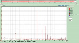
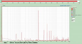
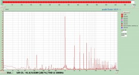
Okay did some measurements at high power levels. While I know that distortion typically increases with power for a given amp, I really don't have any idea how that spectrum "SHOULD" look like. Here is the spectrum of a 1 khz tone at 1Watt, 10 Watts, 20 Watts, and 40 Watts. Is this normal? It seems to me that there is WAY too much higher order harmonics. What can be done to reduce this?
Raising the FET bias to 15mA reduced the THD at 40W down to 0.7368% (not shown due to me not saving the file) The lowest 40Watt THD was 0.6512% at 70mA bias.
Also with the stronger negative rail, the amp will sustain 65W at around 1.1% thd. Dynamic headroom is quite a bit higher but don;t have a consistant way to measure it. I saw 76Watts but I think it is higher. I have to figure out how to get my scope to capture it.
Attachments
I'm not the expert on all this, but I suspect that the stronger negative rail is allowing the CCS to work better.
As far as the distortion of your amp, is the sound disagreeable to you? If not, I would not be too concerned about the "numbers". However, I can say that as long as the total amount of distortion is kept reasonable, the profile becomes more important than the actual amount of distortion. The things that I have done in the past to reduce higher order, and odd order distortion is lower the load seen by the output tubes, and used a resistive load on the first gain stage to promote more even order distortion. I'm not saying "Let's add lots of even order distortion" here, I'm just saying I want the evens to dominate the distortion profile.
Rgs, JLH
Actually the sound of the amp is VERY agreeable. IMHO it is the best amp I have built to date. I guess the reality is that the amp does not play often in the area >10 Watts, and then really only in transients. It certainly has no trouble playing the transients well.
I am realitivley new to the measurement side of things so I don't have alot of experience to draw from. Most of the data I have seen for THD at higher power levels is plotted THD vs. frequency. I have never really analyzed at this level of detail so I don;t know if what I see is "normal". I certainly don't see it to this level when I compare to my Rotel. However, it is SS and I am sure has TONS of feedback.
My goal is to minimize overall distortion to the best possible without the use of feedback. (Or at least not use feedback to eliminate distortion).
I have a hypothesis that some of what I see is the result of my output tubes being too close to the OPT. Other areas of concern for me is the signal wires, feedback wires, and parasitic capacitance of the FET/CCS's mounted on the heat sinks. Another hypothesis (although not likely) is that the input tube is operating at too low of a bias so that at higher power levels the feedback is driving the tube into positive grid on the other hand I am pushing the LED to too low of a current to remain linear. The input tube is biased at 4mA. I do plan on testing the latter.
I have ordered some decent shielded signal wire to test one of the hypothesis, but the other concerns are a little harder to change or test at this point without major redo of the amp plate.
Disclaimer:::::
If some of my ideas are hairbrained and reflect my lack of knowledge I appologize in advance. It reflects where I am at in the learning curve and shows what I need to study further.
If more bias current through your input tube increases the hiss at a point, stop just below that threshold. Also see about loading your first stage with a resistor instead of an anode CCS. Some other adequate tube types could be checked too. Will change the trend a little, you may subjectively check it out too, but the ballgame is drive scheme of output stage and its plate to plate load. In general it behaves as expected.
I can test the later by running a similar test at 8ohms as that would have the effect of increasing the impedance of the plate to plate load seen by the output tubes.
In regards to the input tube, if I went to a resistive load (for right now using the same tube), would regulation of the supply be in order?
In regards to the input tube, if I went to a resistive load (for right now using the same tube), would regulation of the supply be in order?
Depends on how quiet enough is what it gets now. I was using a Maida for input and splitter in mine, but took it out since RC was enough and the LM317 had a ''texture''. I would use my SSHV if there was any free space, but my build's box is seriously challenged for adding even a choke.
Space is a premium on mine as well.
I'll measue the voltage supply tonight at various power levels to see what it looks like.
For low current HV regulation in limited space, consider the LR8. A small piece of perf board will support the TO92 case IC, along with the ancillary parts.
Eli, That looks good. I need to look and make sure I can't violate the 450V max rating. Power supply will hit 570V under no load. I can't see how the device would see that potential however in the circuit.
Didn't have time to measure tonight, so I really don't know if it would help yet.
I was also thinking of some 0A3 types as I do have some deck space.
Didn't have time to measure tonight, so I really don't know if it would help yet.
I was also thinking of some 0A3 types as I do have some deck space.
Last edited:
Bit of an update and some good information to share. I have taken quite a few measurements and tried different configurations. I have left the feedback at around 7-8dB. I'll try to summarrize them here.
Smaller Caps did not measure any different and with only a short listening session, found a little wanting in strong Bass area in comparison to the monster caps. I was expecting the smaller caps to be a little more nimble sounding compared to the monsters, but did not notice any difference. I think alot of the has to do with the heavy bypassing with 100uF and smaller film types across the monsters. The smaller caps are quite acceptable however and would have no issues putting them in another build.
The amp is currently running with a 5687 input tube at 10.8 mA bias. I have also regulated the input tube B''+ to 150V prior to the CCS using a OD3. Still looking at a compact way to regulate the B'+ the LTP. The verdict is still out on the 5687 vs. the 12bh7. They both sound good but at the same time different. The 12bh7 is seems quicker and significantly more precise. The sound stage is very specific and stable, while the 5687 is a little more laid back with a much stronger and LF. The sound stage is wider with the 5687 but just not as pinpoint. Both are listenable without fatigue.
I know my next opinion will offend some people, but I don't usually believe in burn in. I think in some cases it is rational and explainable but only for a short period. In this case the 5687 certainly has some extended burn-in and seems to be continuing to do so slightly. I could actually see it in the square wave behaviour over the first couple of days. The sound however is starting to develop more precision.
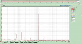
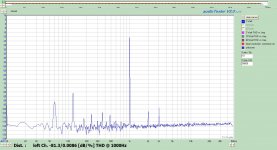
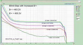
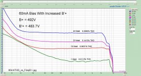
The best THD measure now is 0.0086% 1kHz @ 1Watt 50W = 0dB. Seen in the first graph. For this I maxed out the VA rating of the PT at 80mA bias while reducing the voltage drop between B+ and B'+. The LTP certainly liked the voltage by giving improved THD. The second graph shows THD vs. Frequency at various power levels. I did the same for 60mA bias.
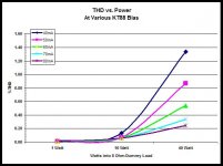
The KT88's definatley like the higher bias currents as it seemed to minimize crossover distortion at high power levels. In the third plot, I summarized the THD performance at various power levels and KT88 bias.
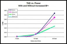
The final graph shows the impact of increasing the voltage to the LTP. Most pronounced at 60mA but I feel that is the result the voltage over 480V. I will need a stronger PT to realize the same improvements at 80mA bias.
Smaller Caps did not measure any different and with only a short listening session, found a little wanting in strong Bass area in comparison to the monster caps. I was expecting the smaller caps to be a little more nimble sounding compared to the monsters, but did not notice any difference. I think alot of the has to do with the heavy bypassing with 100uF and smaller film types across the monsters. The smaller caps are quite acceptable however and would have no issues putting them in another build.
The amp is currently running with a 5687 input tube at 10.8 mA bias. I have also regulated the input tube B''+ to 150V prior to the CCS using a OD3. Still looking at a compact way to regulate the B'+ the LTP. The verdict is still out on the 5687 vs. the 12bh7. They both sound good but at the same time different. The 12bh7 is seems quicker and significantly more precise. The sound stage is very specific and stable, while the 5687 is a little more laid back with a much stronger and LF. The sound stage is wider with the 5687 but just not as pinpoint. Both are listenable without fatigue.
I know my next opinion will offend some people, but I don't usually believe in burn in. I think in some cases it is rational and explainable but only for a short period. In this case the 5687 certainly has some extended burn-in and seems to be continuing to do so slightly. I could actually see it in the square wave behaviour over the first couple of days. The sound however is starting to develop more precision.
The best THD measure now is 0.0086% 1kHz @ 1Watt 50W = 0dB. Seen in the first graph. For this I maxed out the VA rating of the PT at 80mA bias while reducing the voltage drop between B+ and B'+. The LTP certainly liked the voltage by giving improved THD. The second graph shows THD vs. Frequency at various power levels. I did the same for 60mA bias.
The KT88's definatley like the higher bias currents as it seemed to minimize crossover distortion at high power levels. In the third plot, I summarized the THD performance at various power levels and KT88 bias.
The final graph shows the impact of increasing the voltage to the LTP. Most pronounced at 60mA but I feel that is the result the voltage over 480V. I will need a stronger PT to realize the same improvements at 80mA bias.
Attachments
- Status
- This old topic is closed. If you want to reopen this topic, contact a moderator using the "Report Post" button.
- Home
- Amplifiers
- Tubes / Valves
- OPUS 5.0 A Modern Mullard