I'm still pretty confused how to wire this transformer up for the I/V Stage (both 200-250V and 9V connections):
R-Core R80-36
260-230-0-230-260(90mA). 2.5-0-2.5(3A).(3.15-0-3.15)X2(3A)
Anyone want to help out someone thats still learning? It the only thing stopping me from test the dac..
Cheers in advance..
R-Core R80-36
260-230-0-230-260(90mA). 2.5-0-2.5(3A).(3.15-0-3.15)X2(3A)
Anyone want to help out someone thats still learning? It the only thing stopping me from test the dac..
Cheers in advance..
I'm still pretty confused how to wire this transformer up for the I/V Stage (both 200-250V and 9V connections):
R-Core R80-36
260-230-0-230-260(90mA). 2.5-0-2.5(3A).(3.15-0-3.15)X2(3A)
Anyone want to help out someone thats still learning? It the only thing stopping me from test the dac..
Cheers in advance..
It is ok!
You use 5 v/3A + 3.15 v/ 3A for filament!
It is ok!
You use 5 v/3A + 3.15 v/ 3A for filament!
So how would I wire that up tho?
For the 2.5V/3A it goes blue wire, brown, blue
For the 3.15V/3A it goes glay, black, gray
for the 260v - 230v - 0v - 230v -260v is goes green, violet, orange, violet,green
Hi all!
Last sunday I was sent PCB DAC-end2 to all friend! Thank you very much!
Hi m461c14n!
No I have only : ( some PCB)
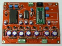
PCB DAC-END
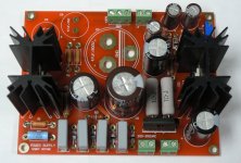
PCB Salas shunt for DAC
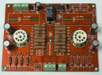
PCB I/V stage.
No have PCb supply for IV, I think you use Salas HV, it is better the sound!
Quanghao
Hi Quanghao,
Will you make the PCB supply for I/V again, if you do
I'll wait till all PCB complete.
Thanks
Just sharing
An externally hosted image should be here but it was not working when we last tested it.
My friend uses Nelson Pass D-1 (replacement for Supply + IV Stage) for my DAC End 2.
But it hasn't worked well. He said the problem is on D-1.
(He'll find what really happened later)
Sound output ( Right and Left channel) isn't at the same level.
Would be delighted to know the result. My plan is to use Pass's D-1 as I/V stage also. Actually I hate tubes.

Would be delighted to know the result. My plan is to use Pass's D-1 as I/V stage also. Actually I hate tubes.
Let us wait, cause my friend work for it
A question about the transformer.
Do you think it's a bad idea to have a single transformer for the DAC and the tubes, with multiple secondaries ?
Thanks,
Davide
Hi Davide,
I've been discussing about this issue back on this thread. It is not a bad idea but having separate transformers is an improvement. You see the DAC is one but the modules are four:
Digital interface (with its own PSU)
Digital to analog conversion (with its own PSU) the source!
High voltage gain stage (with its own PSU) and
Heater (with its own PSU).
It has been design so they don't get jammed together so it is better continue all the way to the return of the signal, that is the transformer(s). Single core transformer technically allow different kind of return signal on different windings to jam magnetically. That's why separate is better. I'm not saying to reach the absolute but a balance and not shortcuts.
IMO I would keep I/V stage +heater one transformer, Digital input one small transformer and Digital to Analog another small one.
Last edited:
Nice build Flocchini!
Did you omit the filter completly?
Also you seem to leave out R30-R33?
Did you try the I/V without Adamus LED mod?
Great to more and more people get there Dac-End singing
I did omit the filter and I left out R30-R33. I may do the experiment and put them in although I am quite happy with the sound.
I also started with the Adamus mod. I was intrigued by Adam's comments and follow-up discussion.
This is a great project. There are potential changes that could be made. Part of me just wants to listen to the music.
Thanks for the reply.
I will also try Adamus LED-mod eventually, but now I just want to get to know the sound of this DAC also. The sound is very addictive.
It's indeed a great project with great "modding" potential
Thanks for the reply.
I will also try Adamus LED-mod eventually, but now I just want to get to know the sound of this DAC also. The sound is very addictive.
It's indeed a great project with great "modding" potential
Yes, I agree the sound is very addictive and very refreshing. I really enjoy 6pm to 1am every day, never tired to listen and I switch off with regret. One of the mods I'm waiting is also the I/V stage power supply upgrade to Shunt Regulator, constant current heater supply and Adamus mod(but with TL431 instead of LEDs). Bye Bye caps.
Last edited:
Yes, I agree the sound is very addictive and very refreshing. I really enjoy 6pm to 1am every day, never tired to listen and I switch off with sacrifice. One of the mods I'm waiting is also the I/V stage power supply upgrade to Shunt Regulator, constant current heater supply and Adamus mod(but with TL431 instead of LEDs).
I for one would be very interested in your results.
I did omit the filter and I left out R30-R33. I may do the experiment and put them in although I am quite happy with the sound.
I also started with the Adamus mod. I was intrigued by Adam's comments and follow-up discussion.
This is a great project. There are potential changes that could be made. Part of me just wants to listen to the music.
@flocchini
Can you show us how to do "ADAMUS MOD"
is it on Salas Board?
It would be very nice if u post with pic ( like lampizator did, with some arrows points some component you've modded)
So how would I wire that up tho?
For the 2.5V/3A it goes blue wire, brown, blue
For the 3.15V/3A it goes glay, black, gray
for the 260v - 230v - 0v - 230v -260v is goes green, violet, orange, violet,green
Hi CustomHT,
I have the same transformer as yours, R80-36. I haven't connected yet since I'm still waiting for parts that I ordered.
This is how I will connect it
You have 2 center tap 3.15V/3A per winding, Gray, Black Gray
You have 1 center tap 2.5V/3A per winding, Blue, Brown, Blue
To make it 8.15V for the heater filament, you only need the 2 Blue wires, ignore the Brown wire just insulate the end of it. That gives you 5Vac/3A. Then connect one of the blue wires, to whichever 3.15V center tap you want to use, to Gray wire and the black wire will be 0V reference. Measure it with the voltmeter and if you don't get 8.15V, you might want to reverse the connection of black and Gray, as what housing had mention earlier. It might be out of phase. You were also asking if you can parallel the 3.15V winding. I think you can but this will become 6A which I don't recommend.
In regards to the 260Vac, I think you can parallel the winding to achieve the maximum current rating, tie up Green and Green wire and orange will be your 0V reference.
Let's consult with the veterans here. Guys, correct me if I'm wrong. I'm just trying to help CustomHT. I know he asked this question like 3 times already and nobody had given him a detailed answer of the transformer connection.
Thanks,
Fred
Hi CustomHT,
To make it 8.15V for the heater filament, you only need the 2 Blue wires, ignore the Brown wire just insulate the end of it. That gives you 5Vac/3A. Then connect one of the blue wires, to whichever 3.15V center tap you want to use, to Gray wire and the black wire will be 0V reference. Measure it with the voltmeter and if you don't get 8.15V, you might want to reverse the connection of black and Gray, as what housing had mention earlier. It might be out of phase. You were also asking if you can parallel the 3.15V winding. I think you can but this will become 6A which I don't recommend.
Thanks,
Fred
I have no practical experience with this transformer, but I do think that's the correct way of getting the filament AC voltage.

In regards to the 260Vac, I think you can parallel the winding to achieve the maximum current rating, tie up Green and Green wire and orange will be your 0V reference.
Thanks,
Fred
I think you can't parallel the 260V AC like that.
Use 2 diodes as a full wave rectifier at each green wire instead of a bridge rectifier to get the rectified high DC voltage, orange will be your 0V reference.
Last edited:
- Status
- This old topic is closed. If you want to reopen this topic, contact a moderator using the "Report Post" button.
- Home
- More Vendors...
- Quanghao Audio Design
- OLD THREAD DAC End by Andrea Ciuffoli