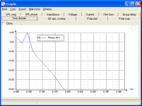
More confusion. According to the ETC in LspCAD, a BW4-1000 highpass should be 30dB down in less than .2msec. I'm not sure what scale JM is using but the 512 FFT looks like it's showing that decay rate better than the 128 FFT which is far too slow to decay.
Attachments
Very clever, Jean-Michel!I created the multiresolution wavelet to approximate CSD, to have better comparison with other forum members. Now you have approached it from the other direction
- Elias
I love to see that great Olympic spirit here !
Might be we should elect an international committee in a subsequent thread for choosing the winners !
My 2ct are at their disposal....
LOL
Michael
Last edited:
Hello Catapult,
In the 3 CSDs for a Butt 4th order 1kHz I gave, the vertical (time) scale is not the same.This is due to the fact that the FFT length is not the same (the longest FFT length gives leads to a time widen CSD.
CSD is probably not the best tool to see how energy decay because we have to use some apodization (no apodization is equal to a rectangular window with all the rippling and others artifacts related to that kind of window).
Best regards.
Jean-Michel Le Cléac'h
More confusion. According to the ETC in LspCAD, a BW4-1000 highpass should be 30dB down in less than .2msec. I'm not sure what scale JM is using but the 512 FFT looks like it's showing that decay rate better than the 128 FFT which is far too slow to decay.
Hello Catapult,
There is not such relation between the FFT length of the CSD and the width of the frequency interval used by Arta for the CSD.
Remember that CSD uses a sliding (with time) FFT using a FFT window having a given width and shape FFT. But for every frequency on the CSD graph that width is the same (that's why for an Impulse Response approaching a Dirac the CSD should look as a rectangle (horizontal and red with ARTA).
Arta doesn't allow us to choose the number of frequencies at which the sliding FFT is performed so the resolution is a bit weak. (If Ivo Mateljan could increase the number of frequencies on the CSD graph it will be very nice!).
Best regards from Paris, France
Jean-Michel Le Cléac'h
JM, your settings seem to work but I don't understand them (nothing new for me
48000/128 gives a 'real' frequency resolution of a data point every 375 Hz. That seems too coarse to be very useful.
128/48000 gives a sample length of 2.67 msec and then we are applying a filter/window with rise and fall times of 1 msec each.
First we threw away the low frequencies with the small sample and then we are throwing away the high frequencies with the large apodizing time. How are we left with any useful information?
Help!!!
Last edited:
Thanks Jean-Michel. Could you post a PIR or WAV of your Butterworth impulse so I could play with it in ARTA?
Here are some additional *.PIR files to play with - corresponding to the DCX filters I measured and published at :
http://www.diyaudio.com/forums/multi-way/161627-horn-honk-wanted-2.html#post2111876
Would be nice to perform better CSD "gating" as I did back then...
http://www.kinotechnik.edis.at/pages/diyaudio/GD_HighPass/DCX_filter/HP_Gauss6_1kHz.pir
http://www.kinotechnik.edis.at/pages/diyaudio/GD_HighPass/DCX_filter/HP_Bess12_1kHz.pir
http://www.kinotechnik.edis.at/pages/diyaudio/GD_HighPass/DCX_filter/HP_Butt12_1kHz.pir
http://www.kinotechnik.edis.at/pages/diyaudio/GD_HighPass/DCX_filter/HP_LR12_1kHz.pir
http://www.kinotechnik.edis.at/pages/diyaudio/GD_HighPass/DCX_filter/HP_Butt18_1kHz.pir
http://www.kinotechnik.edis.at/pages/diyaudio/GD_HighPass/DCX_filter/HP_Bess24_1kHz.pir
http://www.kinotechnik.edis.at/pages/diyaudio/GD_HighPass/DCX_filter/LP_Butt24_1kHz.pir
http://www.kinotechnik.edis.at/pages/diyaudio/GD_HighPass/DCX_filter/HP_LR24_1kHz.pir
http://www.kinotechnik.edis.at/pages/diyaudio/GD_HighPass/DCX_filter/HP_Butt48_1kHz.pir
http://www.kinotechnik.edis.at/pages/diyaudio/GD_HighPass/DCX_filter/HP_LR48_1kHz.pir
Myself would like to do wavelet analysis on them – but I don't expected that to happen any soon .
LOL
But as we see mostly GD changes and do hot have to deal with reflections here, CSD should do equally well...
Had some time to do home work
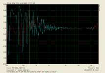
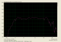
Here are how high pass filters perform.
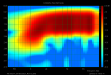
Instead of group delay, I show cumulative spectrum decay in the common form and also in its sonogram variant.
This to me – is in a first step - more intuitively to grasp as a difference in behaviour though I do not forget about GD at all.
The idea behind is that we might be as sensible to shift of origin from GD as we are possibly for a long decay in the time domain.
I know, electrically this is quasi "one and the same" or maybe better put "two sides of the same coin" but nevertheless I would like to bring in this additional aspect .
Basically the following plots show my measurements of all filters available from DCX at 1kHz - in lack of a versitale analog filter source.
All plots are what the text says, starting out with Gaussian 6dB over Bessel Butterworth and Linkwitz Riley up to 48dB


######


######


######


######


#######


#######


#######


#######


#######


Sadly we do not have Chebyshev filters with DCX
We clearly see that there is a huge difference in the time domain regarding decay at HP (XO) frequency.
The sharper and the steeper the HP filter is chosen the more pronounced and prolonged is decay time.
If we now look at the cut off of a horn with an XO set ~1 octave higher – it might be obvious that this "ringing" still will be audible and contribute to horn honk as its by no way compensated by a mating low pass (as is in XO application) – what you think ?
PS:
By the way, I digged up John Kreskovky's page on the matter (related to XO only):
http://www.musicanddesign.com/Stored_energy_2.html
Michael
Michael
Last edited:
"Arta doesn't allow us to choose the number of frequencies at which the sliding FFT is performed so the resolution is a bit weak."
???
FFT length(size) IS the number of frequency bands you get out, no more no less.
Do you mean the the frequency (time between samples) of the moving window?
???
FFT length(size) IS the number of frequency bands you get out, no more no less.
Do you mean the the frequency (time between samples) of the moving window?
If we now look at the cut off of a horn with an XO set ~1 octave higher – it might be obvious that this "ringing" still will be audible and contribute to horn honk as its by no way compensated by a mating low pass (as is in XO application) – what you think ?
Hello,
One way to compensate this effect in the horn, it's to have a cut off frequency (Fa) and a frequency resonance of driver (Fs) equal:
Annexe 2
It reduces the harmonic distortions too.
Hello,
One way to compensate this effect in the horn, it's to have a cut off frequency (Fa) and a frequency resonance of driver (Fs) equal:
Annexe 2
It reduces the harmonic distortions too.
I'm in general on the same trip that we'd possibly better off with a (response shaped) "single & soft" HP filter function regarding GD – I would not have concluded that from your plots though.
Would be interesting if you could demonstrate the benefits of your conclusions on "real" horns.
Possibly the same "high f-res" driver on a horn ~ the same cut off - and on a horn (same contour) with way lower cut off ?
Michael
Right. ARTA interpolates between the data points to plot on a log scale but the 'real' resolution is a data point every (sampling rate)/(FFT size) Hz. You can see the resolution on the CSD charts as the lowest frequency plotted. Increase the FFT size and the chart starts at a lower frequency.FFT length(size) IS the number of frequency bands you get out, no more no less.
I played with Michael's impulse responses of electrical filters a bit and concluded that it's not really possible to get a CSD in ARTA without artifacts. Making (apodizing time)/(FFT size) smaller gives a decay rate that looks right at high frequencies but it introduces other low-frequency artifacts.
Last edited:
Michael said:I'm in general on the same trip that we'd possibly better off with a (response shaped) "single & soft" HP filter function regarding GD – I would not have concluded that from your plots though.
- FWIW, ( because it's a little bit off-topic ) , but I too would like to see Thend post some GD plots that would provide some sort of "PROOF OF CONCEPT" for this idea / ( of matching Fa/Fc to Fs ) .
- I'm not challenging the concept since I know JBL does something similar ( these days ) for some of their world class SOTA systems .
- Here's a group delay plot derived from Panos posted IR ( wave file ) for the 806 on the Dayton , 2-bolt exponential . Remember his HP was down around 400 hz ( I think ) & was 3rd order ? .
- I've superimposed his GD over a GD from my Altec 802-8T mounted to one of my Sammi SH-350 horns ( which is same horn as the Dayton, I believe , look here ! ) .
- My HP is a single cap which is effective at around 1K ( I believe ) .
- Getting the FR of this combo to be this flat was quite simplistic / just a simple RC contour circuit ( no LCR notches ) . I don't recommend others buy the horn since it's very directional / I use it to test a drivers on axis performance / that's it .
- Anyways, one can see the effect of Panos higher order HP in the GD curve when compared to my single pole filter . ( His Group Delay is Blue while mine is Red ) .
- Is it just me ? or does anyone else think that the CSD "time-swelling" below 2K is all attributable to my HP filter ?
- Anyways, I'm gone till next Friday / have fun !
> cheers EarlK
Attachments
Hello,
It's obvious; the comb filtering of the first plot is reduced at Fs with the tube, thus lesser reflection (near driver), lesser delays.
That's means the max absorption of the driver (microphone) is at Fs (this I measured), therefore it is preferable to tune with the horn acoustic cut-off because that is where of max reflection (this I measured) in the usable bandwidth.
But I didn't say we can applied a lower cut-off, because the 1,5.Fa is already the "theorical", "ideal" cases.
In real, the majority of horns don't respect the condition of lesser reflections, so for its the 1,5.Fs is optimistic if we care about GD.
Possibly the same "high f-res" driver on a horn ~ the same cut off - and on a horn (same contour) with way lower cut off ?
It's obvious; the comb filtering of the first plot is reduced at Fs with the tube, thus lesser reflection (near driver), lesser delays.
That's means the max absorption of the driver (microphone) is at Fs (this I measured), therefore it is preferable to tune with the horn acoustic cut-off because that is where of max reflection (this I measured) in the usable bandwidth.
But I didn't say we can applied a lower cut-off, because the 1,5.Fa is already the "theorical", "ideal" cases.
In real, the majority of horns don't respect the condition of lesser reflections, so for its the 1,5.Fs is optimistic if we care about GD.
One interesting ETC comparison between direct driver and a horn attached.
An externally hosted image should be here but it was not working when we last tested it.
Some more food for thoughts regarding "quarter wave honk", guys !
Its been fair temperatures today – though slightly more windy than I would have liked - so I did some "outdoor" measurements
Below we see the complete horn honkers form
0 deg (quarter wave transmission line)
over 60 deg and 120 deg included
to 180 deg (open baffle)
as seen in the pix
http://www.diyaudio.com/forums/multi-way/161627-horn-honk-wanted-4.html#post2118074

all "horns" have the same contour length of ~20cm / 8"
Here we go :
(no gating for any plot)
conical 0 deg included (quarter wave transmission line - no round over)
http://www.kinotechnik.edis.at/pages/diyaudio/GD_HighPass/conical/honker_0deg_deg+0.pir
http://www.kinotechnik.edis.at/pages/diyaudio/GD_HighPass/conical/honker_0deg_deg+0.txt


conical 60 deg included (no round over)
http://www.kinotechnik.edis.at/pages/diyaudio/GD_HighPass/conical/honker_60deg_deg+0.pir
http://www.kinotechnik.edis.at/pages/diyaudio/GD_HighPass/conical/honker_60deg_deg+0.txt


conical 120 deg included (no round over)
http://www.kinotechnik.edis.at/pages/diyaudio/GD_HighPass/conical/honker_120deg_deg+0.pir
http://www.kinotechnik.edis.at/pages/diyaudio/GD_HighPass/conical/honker_120deg_deg+0.txt


conical 180 deg included (open baffle - no round over)
http://www.kinotechnik.edis.at/pages/diyaudio/GD_HighPass/conical/honker_180deg_deg+0.pir
http://www.kinotechnik.edis.at/pages/diyaudio/GD_HighPass/conical/honker_180deg_deg+0.txt


Not often seen structured that way – eh ?
Elias, if you have some time left, would love to see that quarter wave reflections with better resolution in the time domain form wavelet analysis...
Michael
Its been fair temperatures today – though slightly more windy than I would have liked - so I did some "outdoor" measurements
Below we see the complete horn honkers form
0 deg (quarter wave transmission line)
over 60 deg and 120 deg included
to 180 deg (open baffle)
as seen in the pix
http://www.diyaudio.com/forums/multi-way/161627-horn-honk-wanted-4.html#post2118074
all "horns" have the same contour length of ~20cm / 8"
Here we go :
(no gating for any plot)
conical 0 deg included (quarter wave transmission line - no round over)
http://www.kinotechnik.edis.at/pages/diyaudio/GD_HighPass/conical/honker_0deg_deg+0.pir
http://www.kinotechnik.edis.at/pages/diyaudio/GD_HighPass/conical/honker_0deg_deg+0.txt
conical 60 deg included (no round over)
http://www.kinotechnik.edis.at/pages/diyaudio/GD_HighPass/conical/honker_60deg_deg+0.pir
http://www.kinotechnik.edis.at/pages/diyaudio/GD_HighPass/conical/honker_60deg_deg+0.txt
conical 120 deg included (no round over)
http://www.kinotechnik.edis.at/pages/diyaudio/GD_HighPass/conical/honker_120deg_deg+0.pir
http://www.kinotechnik.edis.at/pages/diyaudio/GD_HighPass/conical/honker_120deg_deg+0.txt
conical 180 deg included (open baffle - no round over)
http://www.kinotechnik.edis.at/pages/diyaudio/GD_HighPass/conical/honker_180deg_deg+0.pir
http://www.kinotechnik.edis.at/pages/diyaudio/GD_HighPass/conical/honker_180deg_deg+0.txt
Not often seen structured that way – eh ?
Elias, if you have some time left, would love to see that quarter wave reflections with better resolution in the time domain form wavelet analysis...
Michael
Last edited:
Elias, if you have some time left, would love to see that quarter wave reflections with better resolution in the time domain form wavelet analysis...
Actually not only better resolution in the time domain *only* but also in the frequency domain !
As is easily be seen for the "transmission line horn" the CSD is way too smooth in frequency compared to the frequency plot.
So the 128 samples needed to get lowest artefacts (as we were taking before) swamps all details we possibly are interested in – actually from that CSD only, we would conclude that speaker should sound even "decent" – no ?
Good stuff. Nice work guys.
BTW, my latest measurements were all done with an active 400Hz, 2nd order, Butterworth high pass.
Thanks
I gave the NEO3W a hard time, performing all above measurements of mine without *any* HP filter.
Michael
Last edited:
- Status
- This old topic is closed. If you want to reopen this topic, contact a moderator using the "Report Post" button.
- Home
- Loudspeakers
- Multi-Way
- Horn Honk $$ WANTED $$