...what "higher PSU voltage" means. ...
Buffer on preamp's output works at +24V (equiv. to +/-12V).
That's 33% higher than +/-9V.
Buffer on preamp's output works at +24V (equiv. to +/-12V).
That's 33% higher than +/-9V.
OK, I understand. However, these buffers aren't the issue - they are already built (twice, actually) following your schematic (and hence are at 24V as you say, and have 10R on the CCS source and not the upper jfet.). My question is about the use (or not) of source resistors in the filter buffers, which will all be at +/- 9V.
Cheers
Nigel
... the use (or not) of source resistors...at +/- 9V...
Not
juma,
OK thanks. I think I'll do a pair of boards first and try them in the test preamp, see how things go. (I realise you will think I'm worried about nothing heatwise...
") ) I'm interested to know why in this case you see no reason to run them at 10mA....
) I'm interested to know why in this case you see no reason to run them at 10mA.... Cheers
Nigel
the B1 does not specify 10mA. It is designed to run at just under Idss of the lower device and since the upper device is selected to have the same Idss then The bias in the source follower makes Vgs almost zero. When Vgs is exactly zero then you have no output offset.
Juma has substituted bf862 as the device, but the operation is identical.
Run the upper device at it's Idss and you automatically get Vgs = 0V. Job done.
Well not quite. The device parameters will change with temperature. The output offset will wander as temperatures change. That's where Feucht comes in to help.
I have a copy on my PC. If you can't find it I could Email it to you. Email me with your request.
....That's where Feucht comes in to help.
I have a copy on my PC. If you can't find it I could Email it to you. Email me with your request.
Hi AndrewT,
I've found the article "buffer amplifier design" on AnalogZone (archived), and have been (slowly) making my way through it. If that's not the one please let me know. (It's interestig reading anyway... )
Cheers
Nigel
Hi,
sorry, my question might be stupid: I understand the reason for the insertion of a buffer in the feedback loop to lower the high-frequency level for the LP section. But I am not shure why you did not choose the more easy way, a passive LP filter at the output of the LP section. If I do some simulations, those filter slopes look even better, the phase of the signals is better and for the 4th order circuit you get rif of two buffers.
Regards
Flo
B1 active filter completed.
Hi guys,
Though my main aim is a third order two ways filter, with balanced input buffer based on B1 for my big Autographs speakers, I thought about first give a try on the second order filter published by Jacques Merde. I reused a B1 preamp unit and got this:
Picasa Web Albums - mauricio
I used a small daughter board to buffer the LF signal before the attenuator.
Picasa Web Albums - mauricio
It's rather easy to make but it is also more work than expected!
An here is the unit in use:
Picasa Web Albums - mauricio
Sounds transparent to me.
To Jacques: modelling my filter response through Analog Wizard™ Filter: Home (using model opamps) I do not have the rise in LF after the filter point. Do you expect that this rise will be present also in my future third order filter?
Thanks you in advance.
Cheers,
M
Hi maxlorenz,
Thanks for posting the photos. I have a couple of questions...
So the schematic you used is as in post #14? Can you post the schematic you intend on using in your final version?
The green pcb is the daughter board? Looks more like part of the stepped attenuator circuit in the photo... Or did I miss something? (Always a possibility....) Is the TeddyReg at bottom left in the second photo?
Great! Please keep posting your impressions, as you live with it for a while. (I envy you the space to spread out your creations like that... Those of us who live in apartments with several small children are a little more cramped...)
Cheers
Nigel
Thanks for posting the photos. I have a couple of questions...
Hi guys,
Though my main aim is a third order two ways filter, with balanced input buffer based on B1 for my big Autographs speakers, I thought about first give a try on the second order filter published by Jacques Merde. I reused a B1 preamp unit and got this:
Picasa Web Albums - mauricio
So the schematic you used is as in post #14? Can you post the schematic you intend on using in your final version?
I used a small daughter board to buffer the LF signal before the attenuator.
Picasa Web Albums - mauricio
It's rather easy to make but it is also more work than expected!
The green pcb is the daughter board? Looks more like part of the stepped attenuator circuit in the photo... Or did I miss something? (Always a possibility....) Is the TeddyReg at bottom left in the second photo?
Great! Please keep posting your impressions, as you live with it for a while. (I envy you the space to spread out your creations like that... Those of us who live in apartments with several small children are a little more cramped...
)Cheers
Nigel
Hi Nigel (I like your name: so British )
Yes, the schematics is the one on post#14 with the exception that the potentiometer is on the LP section because my woofers are more sensitive than my bookshelf speakers. I decided to put a buffer before the pot since no one answered my previous question about its need...please use the magnifying lens function on Picasa and locate the little pots on the main board. Next to them you shall see a pair of JFETs in a small strip board: those are the buffers.
Note that I installed individual adaptors from DIP sockets to change resistors if needed.
The green board is a relay source selector from twistedpearaudio.com
The third older filter will follow the original schematics on post#14 as I have to attenuate the 106db sensitive tweeters. The filter part itself can be seen on page 4 of Borbely's paper (quoted above; I can send it to you if needed). You can use AD Wizard to calculate the values of Cs and Rs...
The TeddyRegs are indeed those you saw. Now I will start to use only the new version, the SuperTeddyReg, which is even more transparent:
Teddy Pardo home of TeddyCap TeddyXPS power supply for Naim Audio replaces HiCap and XPS
See "articles".
Hope this helps,
Good luck.
M.
(I like your name: so British )Yes, the schematics is the one on post#14 with the exception that the potentiometer is on the LP section because my woofers are more sensitive than my bookshelf speakers. I decided to put a buffer before the pot since no one answered my previous question about its need...please use the magnifying lens function on Picasa and locate the little pots on the main board. Next to them you shall see a pair of JFETs in a small strip board: those are the buffers.
Note that I installed individual adaptors from DIP sockets to change resistors if needed.
The green board is a relay source selector from twistedpearaudio.com
The third older filter will follow the original schematics on post#14 as I have to attenuate the 106db sensitive tweeters. The filter part itself can be seen on page 4 of Borbely's paper (quoted above; I can send it to you if needed). You can use AD Wizard to calculate the values of Cs and Rs...
The TeddyRegs are indeed those you saw. Now I will start to use only the new version, the SuperTeddyReg, which is even more transparent:
Teddy Pardo home of TeddyCap TeddyXPS power supply for Naim Audio replaces HiCap and XPS
See "articles".
Hope this helps,
Good luck.
M.
Hi guys,
To Jacques: modelling my filter response through Analog Wizard™ Filter: Home (using model opamps) I do not have the rise in LF after the filter point. Do you expect that this rise will be present also in my future third order filter?
Thanks you in advance.
Cheers,
M
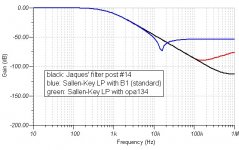
I am not Jaques and I don't know the simulations you mentioned. But if you simulate the Sallen-Key filter with OPs, you will get the same effect but the level will be much lower because of the lower output resistance of the OP.
The reason for the effect is the feedback cap which "bypasses" the buffer and builts a voltage divider with the output resistance of the buffer. This is an effect of the topology itself and you will get it with a Sallen-Key of third order too.
Regards
Flo
Edit: The simulation for post #187 had an error, the post is wrong!
Hi Guys,
I now have a fully functioning active crossover. The sound is no doubt nice, but I am not sure about imaging. I need to play with this a little bit more before I can be sure imaging is not the strong suite of this.
Maxlorenz,
Can you comment on the imaging of your system?
Dinesh
I now have a fully functioning active crossover. The sound is no doubt nice, but I am not sure about imaging. I need to play with this a little bit more before I can be sure imaging is not the strong suite of this.
Maxlorenz,
Can you comment on the imaging of your system?
Dinesh
Dear Floric,
Sorry for the late reply: thank you for your explanation.
Dear Dinesh,
I will be of little help for some time: I got an otitis from swiming pool and my hearing is veiled. I can say that the sound is coming from the room and not the speakers, if that is a guide for you (I think this is the way live music sounds). Imaging is not bad but not pinpointing. I don't care about pinpointing anyway. I can't say more for now.
I am starting my third order filter.
Thanks Mr Pass.
Hi Guys,
I now have a fully functioning active crossover. The sound is no doubt nice, but I am not sure about imaging. I need to play with this a little bit more before I can be sure imaging is not the strong suite of this.
Dinesh
What's your crossover frequ? Have you checked th phase? Try the system with reversed polarity on te tweeters! And check out if you didn't interchange the channels for either the high or the low pass. I did it once and imaging was there but it was horrible...
Flo
Hope you get well soon Max.got an otitis from swiming pool and my hearing is veiled.
I can say that the sound is coming from the room and not the speakers, if that is a guide for you (I think this is the way live music sounds). Imaging is not bad but not pinpointing. I don't care about pinpointing anyway. I can't say more for now.
I have to agree, the imaging in general is OK. It centers nicely, but you cannot pinpoint things for sure.
Just in case people get the wrong opinion that I am selling this short, make no mistake, this is the nicest my speakers have ever sounded. Imaging not withstanding. Years back I had built a Jordan JX92 based MLTL speakers. That would image so well, it would throw sound behind you, a great effect for watching movies. This one will not, but the sound from this will run circles around my old MLTL speakers.
First when I hooked it up I did have the polarity reversed, so I know how it sounds. I think the phase is fine. The image centers well, and you can feel that you are nicely up close to the performers. Neither of which would happen if phase was messed up.What's your crossover frequ? Have you checked th phase? Try the system with reversed polarity on te tweeters! And check out if you didn't interchange the channels for either the high or the low pass. I did it once and imaging was there but it was horrible...
Tweeter (Fostex FF85K) cuts in at 360 and Woofer (Eminence Alpha 15) cuts out at 200. Yes, it is not Linkwitz-Riley configuration, because the woofer is in a H Frame and the tweeter is in open baffle.
Today the sound improved a bit more, I removed a Zobel network in the amp output. That cleaned up the sound quite a bit.
I will play around some more, and see whatelse I can fix.
Here is something odd, during one of the experiments, I removed the power to the crossover, but the amp still had power and it continued to play, really really distorted of course. What struck me was that I had expected the sound to cease, but it did not. I am wondering if there is a problem, some where, somehow. But, on the other hand, if there were major problems, it cannot sound this good. Anyway, experiments continue...
Regards,
Dinesh
the active cross over continued to operate using the energy stored in the smoothing caps.
As the energy got used up, the voltage at the caps and at the supply rails of the crossover dropped.
The voltage dropped such that the signal passing through the crossover started to get clipped, gently at first and becoming more like a variable frequency square wave.
No wonder it sounded horrible.
You should have an instant mute on the crossover that triggers on loss of AC power.
Distortion
Hi Guys,
Last night I put together one channel of a 2-way 4th-order crossover with SK filters on a breadboard. Mounted the buffers on a little piece of perf board, so that they fit in DIP-8 sockets. That worked out very well.
However, my HP analyzer shows that THD exceeds 0.1% at an input level of around 1V. So I went back to my LTSpice simulation and got it confirmed. The signal waveform pretty much matches what I saw on the scope: At 8KHz the lower half-cycle looks more like a triangle.
In the filters, I arbitrarily set R to 1k. What I found out in the simulation is that THD drops with rising R.
So my question is, has anybody found an optimum value for R yet?
I am going to experiment a little on my breadboard tonight.
Manfred
Last edited:
- Status
- This old topic is closed. If you want to reopen this topic, contact a moderator using the "Report Post" button.
- Home
- Amplifiers
- Pass Labs
- B1 Active Crossover