When it comes to resistor distortion. I think that you are at an end to finding anything. Resistors are especially difficult, because they have their own resistance that could potentially obscure the measurement of it with extra noise, both from the resistance noise and its effect on the input stage of the measurement amp. 1K
1K is the dividing line for many test instruments, but 100 ohms would be better.
John
With my AP limited to about 15 volts drive I find using a Wheatstone bridge configuration to compare resistors 500 ohms or so gives me maximum sensitivity without worrying about thermal distortion.
Attached is a word document that shows the reference compared to itself (Lowest level)
A 5% 1/4W carbon film voltage divider pair compared to the reference. This is the middle curve on the third harmonic.
A 1% 1/4W metal film resistor pair compared to the reference. This is the highest third harmonic peak.
The reference is made of two metal film resistors for both the upper and lower parts of the divider. (4 resistors total) The combined value is 500 ohms 1/2 W .7%
Interesting to note the Carbon film has less third harmonic distortion!
Scott & John
I used an aluminum case for this batch of tests.
Attachments
John
With my AP limited to about 15 volts drive I find using a Wheatstone bridge configuration to compare resistors 500 ohms or so gives me maximum sensitivity without worrying about thermal distortion.
Attached is a word document that shows the reference compared to itself (Lowest level)
A 5% 1/4W carbon film voltage divider pair compared to the reference. This is the middle curve on the third harmonic.
A 1% 1/4W metal film resistor pair compared to the reference. This is the highest third harmonic peak.
The reference is made of two metal film resistors for both the upper and lower parts of the divider. (4 resistors total) The combined value is 500 ohms 1/2 W .7%
Interesting to note the Carbon film has less third harmonic distortion!
Scott & John
I used an aluminum case for this batch of tests.
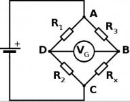
What are the conditions here, this is not the same as the other test? The best way to drive a bridge is with equal and opposite signals so the instrument see only the inbalance signal. What do your numbers here represent? I measured Dale RN55's in 1982 and never saw any voltage coefficient to speak of. With resistors you can make these measurements with a good sound card (XLR inputs).
Also I don't see how you get any output from a bridge unless you have your DUTs connected crosswise (maybe you did that).
Last edited:
What are the conditions here, this is not the same as the other test? The best way to drive a bridge is with equal and opposite signals so the instrument see only the inbalance signal. What do your numbers here represent? I measured Dale RN55's in 1982 and never saw any voltage coefficient to speak of. With resistors you can make these measurements with a good sound card (XLR inputs).
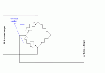
I use the AP's "Balanced" output mode on the low impedance output setting to drive two resistive dividers. The "Balanced" input then gets one side from my reference resistor pair and the other from the Devices Under Test.
By reciprocity I am trying to tweak my reference pair.
I need to learn how to assign a reference value to the db scale. It is reading 23 db higher than my reference voltage. So the resistors are somewhere below -145 db on the third harmonic and nothing else shows up. You can probably get better by another 3 to 6 db depending on how you reference the measurement.
Oh I almost forgot 128 averages!
Crosswise would assume the resistors are perfect. Wheatstone used four strain gauges two under compression two in tension. I can't quite do that. But obviously if the resistors are non-ohmic they would reasonably cancel in a straight bridge circuit. I am looking for discontinuous behavior. That would show up, but I can't say if this is actually showing that.
Last edited:
Hi Ed,
Is it a correct setup?
In that configuration I don't see why there is any output at the thirds. Both dividers see the same voltage on both halves. Can you make certain the input sees no common mode voltage? I might be able to repeat this with some .001% Vishay sealed in oil resistors.
Last edited:
In that configuration I don't see why there is any output at the thirds. Both dividers see the same voltage on both halves. Can you make certain the input sees no common mode voltage? I might be able to repeat this with some .001% Vishay sealed in oil resistors.
Yes the idea is that both inputs should see exactly the same input. My limited test on the accuracy was to have both inputs go to the reference. That was the lowest trace and of course showed the best null at 1K.
Running the test at 7.5 volts lowers the distortion in both D.U.T.s by enough that I have to do 4096 FFTs to get a reading on the change.
I expect that to indicate how much is thermal effects. Of course the better performing resistor pair is the carbon film which is specified as having a much worse tempco than the metal film.
These are preliminary tests before I spend money getting samples and using a buffer amp.
The other test is with 1K and 100 ohm resistors on each side. That may allow for a change that could show what is thermal versus discontinuities.
In the picture, a single DUT would be Rx but the second one should be R1 and there should be a trim for bridge balance. If Rx and R3 are the same they see exactly the same voltage and you only get the difference in the effect between the two. Micro-diode effects should make seconds and other evens anyway.
Attachments
Yes the idea is that both inputs should see exactly the same input. My limited test on the accuracy was to have both inputs go to the reference. That was the lowest trace and of course showed the best null at 1K.
Shorting the inputs to essentially ground and still getting any signal at 1k is worrysome.
Some years ago i saw distortion measurements on resistors from Röderstein. It was 3rd harmonic and the ones with higher wattage rating had less. If i can remember correctly we talk about a level of -140dB. i have no idea how they did it. My friend Dennis Morcroft of DNM goes the other root. He claimes that very small resistors sound better because they do not take up much electric field from the outside. Puzzling.
In the picture, a single DUT would be Rx but the second one should be R1 and there should be a trim for bridge balance. If Rx and R3 are the same they see exactly the same voltage and you only get the difference in the effect between the two. Micro-diode effects should make seconds and other evens anyway.
Yes, that is the classic Wheatstone bridge. I could not find a trim that did not distort the results greatly.
What I am looking at is how a pair of the same type perform as I think they are really used that way although the second resistor in the divider may actually be an active device.
As too looking for micro-diodes, if they show up I will be very surprised. I expect the source of discontinuities to be something else.
BTY at 4096 FFT's the distortions out to the 9th just show up at the screen resolution!
As I think has been discussed the classic methods of measurement may not be valid at very low levels and anomalies may show up.
Shorting the inputs to essentially ground and still getting any signal at 1k is worrysome.
Yes but it was down by 141 db! So sue me it wasn't the -152 resolution of the analyzer. I would expect some reflections from just the case, besides the coupling of the silver wires inside the case being near each other.
Thanks for the input. It is appreciated.
You can download "diffmaker" from the Liberty Instruments, Inc. Home Page website for free for a digital alternative to show differences. I put caps to the test and got differences. the biggest source was tiny differences in value so selecting seems to have merit.
Results are in on the Carbon Film 1/4 Watt 470 ohm resistor pair (940 ohm 1/2W total.) Decreasing the input by 5.5 db as measured by the AP (Changed the send part by 6 db, 15V to 7.51V) decreased the third harmonic distortion by 12 db. This tells me that there is a significant thermal part to it.
Just at the noise threshold and not reliable were the upper harmonics that did not seem to change as much.
So the simple lesson is to use your CF resistors at well less than rated power.
Just at the noise threshold and not reliable were the upper harmonics that did not seem to change as much.
So the simple lesson is to use your CF resistors at well less than rated power.
- Status
- Not open for further replies.
- Home
- Member Areas
- The Lounge
- John Curl's Blowtorch preamplifier part II