I'm quite surprised at that. If the AP does FFT's that slowly you would be far better off taking the data to MATLAB or MATHCAD. You could also do a much better analysis. Larger FFT's give a much better noise floor than averaging small ones. At 96k 4 million points is less than a minute. In an hour you could get 30dB lower noise floor than 4096 4k FFT's. This could easily be set up.
Data set not point!
My MATLAB keeps crashing, it is a when I get around to it kind of thing. I have a major project scheduled for it, but the staff to do it probably won't start for another 15 months.
I have the luxury of turning on the AP and letting it run while I do useful stuff.
Oh BTY the idea of using a comparator to explore behavior ranks up there!
Ed, it seems to me that what you are doing is OK, but how relevant is it? First of all, you are measuring at relatively high voltages. This is good for thermal problems, BUT your distortion seems to be voltage related as it tracks with what would be expected, at lower voltages across the resistor. Any xover type distortion would have to START at -20 to -40 dBV not +20dBV. That is a 50-60dB offset that you will never get over, FOR measuring low level distortion. For high level distortion, you seem to be on track.
Ed, it seems to me that what you are doing is OK, but how relevant is it? First of all, you are measuring at relatively high voltages. This is good for thermal problems, BUT your distortion seems to be voltage related as it tracks with what would be expected, at lower voltages across the resistor. Any xover type distortion would have to START at -20 to -40 dBV not +20dBV. That is a 50-60dB offset that you will never get over, FOR measuring low level distortion. For high level distortion, you seem to be on track.
First I have to select my reference resistors, then I can go to lower levels. I suspect I can increase the sensitivity by at least 60db once the procedure is cleaned up. Then I can go lower.
But the high level data is actually interesting as it shows power limits are a bit lower than expected. A 1/4 watt resistor may not be the best choice for the global feedback resistor in a power amp. Or 5 watts may not be enough for the emitter resistor.
My approach is simple actually do something and see where it leads.
But yes you are right much of this will not be understood by some.
I'm quite surprised at that.
Agreed.
Ed, it seems to me that what you are doing is OK, but how relevant is it? First of all, you are measuring at relatively high voltages. This is good for thermal problems, BUT your distortion seems to be voltage related as it tracks with what would be expected, at lower voltages across the resistor. Any xover type distortion would have to START at -20 to -40 dBV not +20dBV. That is a 50-60dB offset that you will never get over, FOR measuring low level distortion. For high level distortion, you seem to be on track.
-40dBV is do-able if you get the FFT bin size down to a few Hz or less. You need to get the resistor noise down below your signal. -160dBV is 10nV and 1K is 4nV/sqrt-Hz. A BW of 1/16 Hz gives you 1nv per bin. At 96K sampling 2Meg points should do.
Ed, if I read you right, you got 4 times more 3'rd harmonic distortion when you doubled the voltage across the resistor. What did you expect? That is the theoretical prediction based on the mathematical derivation of 3'rd harmonic distortion. I'm I missing something?
I am not sure of your derivation. In a linear system of course there would be no third harmonic distortion. If the deviation were a square term then I would expect the results shown. Somewhere in the back of my mind says since the resistance is fixed the thermal distortion would be a square term as power would follow voltage squared. That is what happened.
I am posting the results of changing the frequency, which also indicates that it almost follows the thermal predictions! Anyone who wishes to may re-post this as a PDF on this website only. I have changed the db scales to reference 15 volts
Interesting to note is some of the higher harmonics do not follow the squaring.
The other issue is that my design goal is 160db S/N for the entire system. At low frequencies and more modest voltages these resistors would not meet that. At 100hz the resistors would be limited to 1/8 power rating and to be sure they were not the limiting factor as low as 1/32 power or 1/128 of a watt!!!
I am willing to assume the thermal distortion may be modeled accurately as levels decrease. So this data is useful in selecting the correct wattage to get the desired level of distortion.
There actually may be a reason some folks find carbon comp resistors work better in their amplifiers. High voltage and low resistance values may actually cause more distortion in some designs!
Attachments
-40dBV is do-able if you get the FFT bin size down to a few Hz or less. You need to get the resistor noise down below your signal. -160dBV is 10nV and 1K is 4nV/sqrt-Hz. A BW of 1/16 Hz gives you 1nv per bin. At 96K sampling 2Meg points should do.
Scott
I can also cheat and just look where I expect the distortion!
Scott
I can also cheat and just look where I expect the distortion!
True, you still need a 1/16 Hz (or so) resolution BW. I think you are talking about two different things, the third harmonic is what you expect because both polarities of input heat the resistor. The amplitude of which goes as power (V**2)
Last edited:
True, you still need a 1/16 Hz (or so) resolution BW. I think you are talking about two different things, the third harmonic is what you expect because both polarities of input heat the resistor. The amplitude of which goes as power (V**2)
Actually it is the ninth that seems to show up when it shouldn't
I am posting the results of changing the frequency, which also indicates that it almost follows the thermal predictions! Anyone who wishes to may re-post this as a PDF on this website only. I have changed the db scales to reference 15 volts
Here you go.
Attachments
I am not sure of your derivation. In a linear system of course there would be no third harmonic distortion. If the deviation were a square term then I would expect the results shown. Somewhere in the back of my mind says since the resistance is fixed the thermal distortion would be a square term as power would follow voltage squared. That is what happened.
I am posting the results of changing the frequency, which also indicates that it almost follows the thermal predictions! Anyone who wishes to may re-post this as a PDF on this website only. I have changed the db scales to reference 15 volts
Interesting to note is some of the higher harmonics do not follow the squaring.
The other issue is that my design goal is 160db S/N for the entire system. At low frequencies and more modest voltages these resistors would not meet that. At 100hz the resistors would be limited to 1/8 power rating and to be sure they were not the limiting factor as low as 1/32 power or 1/128 of a watt!!!
I am willing to assume the thermal distortion may be modeled accurately as levels decrease. So this data is useful in selecting the correct wattage to get the desired level of distortion.
There actually may be a reason some folks find carbon comp resistors work better in their amplifiers. High voltage and low resistance values may actually cause more distortion in some designs!
Very nice Ed! New ground being broken.
BTW Where's the tiny 2nd harmonic coming from? AP residual?
jd
Here you go.
Thanks, I own the adobe software but it is on another computer and I am way to cheap to buy multiple copies. Thanks again!
Very nice Ed! New ground being broken.
BTW Where's the tiny 2nd harmonic coming from? AP residual?
jd
The 1K second harmonic is quite real. I used to have a spike at 18K but I put a catalog under the PC that sat on top of the AP and that went away!
At 100hz one is really a 180hz hum on the 7.5V test the 15V test also shows 2nd that is doubling also. At 1k both are real. This indicates a mechanism that is "balanced" mostly so there may be some reason like a resistor heats faster than it cools or vica-versa.
I wonder...afair there is a IEC standard concerning resistor distortion. Why not follow established procedures?
regards
The question is not about the standard but about the effects that would influence audio design. A standard is designed for multiple users, we may have more specific needs.
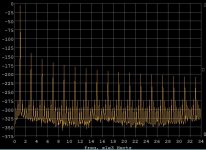
Mathematically this is the spectrum of a perfect 1ppm square law compression. Ignore the numerical noise.
Thanks, pretty much as expected, not quite as measured, not really a surprise as has been mentioned there is some second harmonic, possibly related to thermal radiation.
I am still surprised at the level. It is much greater than I expected and I suspect it will be even worse once I find a more accurate reference.
Simon, you may not have taken the course in EE. But it can be shown that distortion RISES with level, IF it is not Xover distortion. 2'nd harmonic rises directly with input signal. 3'rd harmonic rises as the SQUARE of the input signal. Therefore: 2 times the level, 4 times the distortion WITH 3'rd Harmonic. Scott Wurcer should have told you this.
Simon, and everyone else, I hope I have not confounded you too much. It is true that I had to learn this properly in class with some professor like Dr. R.G. Meyer at UCB, but even techs have seen this effect and its prediction in analog magnetic tape. Think back everyone, to the change in distortion in a magnetic tape at some nominal frequency like 1KHz. For every 6dB increase, the distortion rises 4 times, or +12dB. For every 6dB decrease, the distortion drops to 1/4 the value (-12dB). Look it up in an old book, if you have one around. This is for pure 3rd harmonic distortion, but that is a useful approximation for analog magnetic tape.
- Status
- Not open for further replies.
- Home
- Member Areas
- The Lounge
- John Curl's Blowtorch preamplifier part II