What is happening to the output voltage? It should stabilise at something like +260V* measured at pin 7 of V7 (6GC5). This can be measured at the positive terminal of C56 (8uF 200V - in the phono section away to the left) or at the positive terminal of C54 (1uF 200V cap in the power supply section)
Just for my clarification: it your preamp a SA5 or a SA5.1? That should be printed on the front panel and also on the serial number plate on the back.
*measured relative to ground.
Just for my clarification: it your preamp a SA5 or a SA5.1? That should be printed on the front panel and also on the serial number plate on the back.
*measured relative to ground.
Last edited:
I have the 5.0. A very early model.
I could use some help knowing a good spot to use as ground for measuring?
Had you meant the voltage could "also" be measured at the other two mentioned locations?
Many thanks in advance!
Ed
The reason for asking abut the version is that the power/status indicator LED is driven differently in the two major versions.
A good ground would be the (-) terminal of any of the electrolytic caps in the power supply - they are big and blue!
And, yes, 'also' would have made it clearer
A good resistor for replacing these that isn't too expensive are the Mills MRA-5s. Supposedly 5W non-inductive wirewound. These will fit in place of the Rodersteins without any creative lead bending, etc.
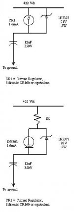
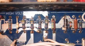
As for the resistors in parallel with the CRD can (Siliconix CR-160 or equivalent), my SA5.1 has a resistor in series with it (before the CRD, assuming I traced the circuit out correctly), but nothing other than the 1N5378 91V zener in parallel with the CRD. Not shown on the schematic I have (which is an SA5, not 5.1 schematic).
I attached a diagram I had done of this at one point, as well as a pic of what this section in mine looked like.
Attachments
Pars, Thanks for the info. I looked at the Mills 5W at Partsconnexion. Couldn't find the values, though can likely mix and match. Will keep looking. Meantime I did order some stocking stuffers for my lads. Nothing like some silver hook-up wire to wake up to Christmas morning. At the same time I ordered some of the 1/2 watt Holco resistors. Found a 49K9 and 24K which should at least be better than what I have in there now.
Then on a ebay buying spree I purchased 23K7 and 49K9 1/4 W 1% 50PPM QTY 100 each SANNOHM RESISTOR. Not familiar with quality of these, and wattage on the low side, but they were on the cheap. Am building up quite a collection!
Then on a ebay buying spree I purchased 23K7 and 49K9 1/4 W 1% 50PPM QTY 100 each SANNOHM RESISTOR. Not familiar with quality of these, and wattage on the low side, but they were on the cheap. Am building up quite a collection!
So far so good...
- The 5651 strikes like a charm and when it is supposed to!
- Green led (looking dimmer?) not bothering me and may just be my imagination as stated before.
- Did change out the 49k9 with a Holco
- Changed out two 1K that looked a little weary in the outboard power supply
- Totally unsoldered cleaned, stripped and resoldered 3 wires (all ends) that were going to my quad of photoflash caps in the outboard power supply. Wires were pretty rough shape.
So am pretty happy. Haven't had chance to double check voltages yet. Still pretty busy around the house and at work. At least able to enjoy music while working at home.
Thank you everyone.
Always be very careful when bending the leads of any Holco brand resistor. The end caps can delaminate from the resistive substrate and it can then also be intermittent. This potential failure issue is there with any resistor but it is especially noted for the Holco resistors.
Tube circuits have enough 'ghosts in the machine' when attempting to repair them, already. So, when bending the leads of a Holco resistor, always keep that in mind and support the lead at where it meets the body and then bend the lead. One way is to use two sets of miniature pliers.
Tube circuits have enough 'ghosts in the machine' when attempting to repair them, already. So, when bending the leads of a Holco resistor, always keep that in mind and support the lead at where it meets the body and then bend the lead. One way is to use two sets of miniature pliers.
Hoping my measurements close enough?
Voltages readings are slightly different in the spots VivaVee suggested I test, but am hoping close enough...
Testing the 5651 tube per diagram VivaVee provided, I get 84 Volts versus the 85-86 Volts suggested
Testing pin 7 of the V7 tube to ground I get 251 Volts instead of 260 Volts suggested.
Hoping I'm close enough?
If done with this, or close to being done, what a feeling of self-satisfaction... of course none of which could be possible without everyone's help!!!
Next up would be a possibly DIY repair of my almost impossible to read Roksan Caspian CD display. An inherent problem from what I've read. Guess would have to jump over to the digital source forum.
Ed
Voltages readings are slightly different in the spots VivaVee suggested I test, but am hoping close enough...
Testing the 5651 tube per diagram VivaVee provided, I get 84 Volts versus the 85-86 Volts suggested
Testing pin 7 of the V7 tube to ground I get 251 Volts instead of 260 Volts suggested.Ed
The range for the regulated B+ (measured at the cathode of V7 = pin7) is 245 to 258 VDC, so everything is OK. Now go enjoy some music.
Hi Ed,
Did you, or anyone else think to check the voltage rating of those resistors by chance? I know this seems like a minor detail, but it's really quite important. You must work from your peak transient voltage or the highest voltage the resistor will ever see. For the record, I did not look these up myself. Also, the voltage breakdown varies by dissipation rating.
Now, why on earth are you using so-called "audiophile" quality resistors? This is an important question as well. You are repairing a power supply for one, one that uses a great deal of post filtering. The proper parts would really be metal oxide, or a metal film with a high enough voltage rating. Personally, I use metal oxide types. Counterpoint used metal film types for the ad copy only.
Another crucial point needs to be made. The output voltage is not that critical. What is important is that it is stable. Fretting about a few volts up or down doesn't make any sense at all.
About those "photo flash" capacitors. Wrong parts again! They became popular amongst "tweakers" as a cheap alternative to what the proper type capacitor should have been. The caps you have in there are not optimized for this circuit use, and do not perform as well as a Sprague, Cornell Dubilier, Illinois - you get the idea. Real capacitors designed for use in real power supplies. They even fit where the board was designed for them.
As for the 5651 tube, the exact specifications are real easy to find on the 'web. You would have seen the expected voltage drop and even seen a graph on many data sheets of voltage vs current. One aspect of these types of references is that every time you strike one, it settles down at a slightly different voltage. Maybe not every time, but they are not expected to have the identical voltage across them every time you fire the same tube up. That means that the exact voltage at the output of the regulator is not important. Also, most circuits are separated by an R-C network. As the average current draw shifts, so will the actual plate supply voltage.
My advice to you is pretty simple. Install the proper parts for the job at hand, the parts you used are not better (for this job). There are no "best parts" that cover for every job. Those photo flash caps really have to go as well.
I think that people replacing parts ought to investigate what the differences between these parts are. Don't bother with "white papers" folks. Look in industry publications. A real product manufacturer will be careful what parts they say are suited for various conditions. This goes for resistor people as well as capacitor people.
I'm still shaking my head over this one.
-Chris
Hi Ed,
I just thought I should mention another design flaw that you should correct in the power supply. Have a look at the first filter capacitor, 100 µF at 500 VDC. Next, using Google, find the data on the 6CA4 rectifier tube. The next capacitor in the filter, also 100 µF and 500 VDC, needs to have it's value adjusted too.
Also, DO NOT use 6BW4 tubes, even if you have rewired the socket to accept them. They are rated for a lower maximum current and they also have a higher internal resistance. This tube will run hotter and your B+ will be slightly lower. The problem is that this tube is a less robust tube than the original 6CA4. The 6CA4 was a wise choice, but the filters are poorly suited for the job at hand. Proof of this is in the recommendation of the designer that the weaker tube (6BW4) "sounds better". There are technical reasons why this is the case, but I doubt one could clearly hear the difference. Your wallet would though. Possible tube shorts and a short lifespan of the tube will be your reward for going that route.
Here is the data sheet for an RCA branded 6CA4. Note also that there is supposed to be resistors in series with each plate. Please, do cross check this with other major manufacturer's data sheets as well.
-Chris
Attachments
Roederstein MK3 resistors (the blue bodied ones originally used in the SA5) were rated at 0.5W and 300V. So that is the basic spec that you need to meet or exceed. The Holco H4, which is probably what you have purchased are also rated at 0.5W and 300V.
You were not specific about where you fitted the photoflash caps. The potential problem is that these caps have a low ESR for rapid discharge in their intended application but were not designed for continuous duty combined with long life. The low ESR is also a real problem for regulator circuits not designed for such caps.
This is a classic issue that is played out in these forums since Noah was a babe and will undoubtedly continue til the sun fades. If the circuit is designed properly to use low ESR caps, then they are a good idea. If the circuit was not designed with such caps in mind, then they may/may not be ok. If you have the skill/experience/test equipment to make that determination, then proceed. And to burst a few bubbles - listening doesn't count until after the engineering is done properly.
I'll depart from Chris's view a bit here on the spendy parts you have bought - feel free. But you are advised to take care that any departure from the original part choice doesn't adversely affect the safety, functionality or reliability of the unit.
Hi Alan,
We don't really disagree here. My entire point is that people tend to install parts without knowing anything at all about these parts. The other half of this is that an "improved" part is improved - how? How do those improvements impact the device in this application?
Wouldn't you agree?
BTW, this circuit was "designed" entirely by ear. Those capacitors are not designed in and are poor choices as you have pointed out. This brings me to my next point. Any thoughts on those capacitor values?
All,
Until you (anyone who does any work on electronic equipment) understand what factors are at play with the parts, and the circuits - don't touch them. Not even if your favorite tweaker or reviewer gives it the thumbs up. It's amazing how many people will give advice with no real understanding about what is going on.
Price has zero relationship with the suitability of a part to an application, make a big sign. A part with "improved construction" or lower noise (or just plain audiofool favorites) may perform poorly in a specific application. I would worry about voltage breakdown, derating and robustness when choosing parts. There are some resistors that have voltage breakdown ratings in the 150 VDC area (nice eh?) and some that go up to 600 VDC and higher. AC voltage ratings will be much lower.
-Chris
I recalled that Michael Percy notes in his catalog wrt th the Holco H4s:
*H4 (RN-60) .5 watt @70°C, 300VMax, TCR is 50ppm
*Caution!!! As the failure rate with the H4 (not PRP) increases with voltage, limit the maximum applied voltage to 150VDC or less.
I personally like the Roederstein MK3s... too bad they got discontinued when Vishay bought them.
*H4 (RN-60) .5 watt @70°C, 300VMax, TCR is 50ppm
*Caution!!! As the failure rate with the H4 (not PRP) increases with voltage, limit the maximum applied voltage to 150VDC or less.
I personally like the Roederstein MK3s... too bad they got discontinued when Vishay bought them.
Oops. Yes it is the H4 I used in the 49k9 spot and spec'd as you say. Were only 16 cents each. Considering "Michael Percy's" notation should I replace with something of higher wattage? I do have higher wattage on hand, but the resistors are quite large (in size).
For clarification, it is in the OUTBOARD powersupply that I replaced the existing 4 photoflash capacitors. They had been in there since the late '80s (originally replacing the 2 silver cans by my dealer/tweaker friend. 2 each of 200MFD330V-PF). Chris, are these the capacitors whose values I should reconsider relative to the 6CA4 as well as getting those PF caps out of there altogether? To be honest, I am not sure if I will be able to figure out correct values using the supplied information, but will give it a whirl.
I must admit, the original tweaker/counterpoint dealer put those PF caps in sometime in the late 80's. He also replaced a couple of resistors here and there with Holcos. I was just following what I thought he would do this time round.
Whatever he did then, I was able to leave my preamp on all the time, with nary an issue. Just turning it off during thunderstorms, or when cleaning/testing tubes. That's about 20 years of life with those PF caps in there.
I actually gave him a call when the 5651 first started acting up, but he was going to be tied up for a month, so I ventured here. He is no longer a dealer, but still dabbles like a mad scientist.
He would probably have a good laugh at everything I've been going through!
Ed
Michael Percy didn't put that note in for no reason; must have had some failures reported back to him? I have used Holco H4s and the smaller version (H8?), I think I still have these in for the phono loading resistors in my SA5.1.
As for the caps, what Chris was telling you was the first cap following the 6CA4 is supposed to be 50uf or less. The stock caps for C77/78 (the original large silver cans) were spec'd as a C-R-C filter, with the caps being 100uf/500Vdc with a 500 ohm 5W resistor between them. Since these caps usually see ~450Vdc or so, the photoflash caps you are using are too big (200uf) and possibly too low of voltage rating (is the 330V AC or DC rating?).
From simulating this supply in Duncan's PSU designer PSUD2, the stock 100uf first cap causes slightly too high of current on startup. I replaced the first cap in mine with a 47uf/500Vdc Elna Cerafine; the second cap is a 100uf/500Vdc Elna Cerafine. In the PSU designer, using 2x100uf caps here does cut the ripple in half; since the overload is slight, I may go back to the 100uf for the first cap. The bottom line (and I'm sure Chris will echo this and has much greater knowledge of tube circuits) is the PSU for most Counterpoint gear is not designed properly. Because the case is so small, it is difficult to do much better without starting over.
Chris had suggested to me awhile back to try a small resistor preceeding the first cap (C77). I could never get anything to work out well in PSU designer, so have never attempted this. One cap you could look at would be the Panasonic TS-UP 500V series Aluminum | Digi-Key; these are relatively small physically, and are of appropriate ratings. I also have a pair of these (100uf/500Vdc).
Last edited:
starting to make sense
I think I am starting to understand the tweak done 20 years ago.
The 2 original cans would have been as you say (100uf/500Vdc).
Each can was replaced with a pair of 200uf/330Vdc-PF hooked up in series (2 PF caps 200uf/330V-PF in series would work out to 100uf/660V).
I think the math is right? And as Chris mentioned, photoflash caps might have been a "trend" at the time.
And that essentially how I am running it now except that I have 4 new PF caps in there.
Right now I am really happy that things are actually functioning normal. However with potential weakness that I should address.
Everyone's comments are extremely appreciated. I hope someday I can pitch in and come to someones aid!
Ed
photoflash caps
oh oh. doing some readin on the net. looks like there was a time and place where the PF caps were a good option compared to what was available at the time. That was then. Now the construction ain't what it used to be and much better options available.
Scary thought I would have left em in there.
I get to do more soldering!
ED
- Status
- This old topic is closed. If you want to reopen this topic, contact a moderator using the "Report Post" button.
- Home
- Source & Line
- Analog Line Level
- Counterpoint SA5 Preamp Problem