Alright...
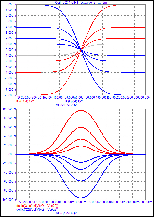
R=BJT LTP
G=JFET LTP
B=NTP
Notes:
1: The NTP derivative would itself be exponential except that the BJT is not purely exponential because of IKF, parasitic properties...
2: Gain of the LTP and NTP is the same when their bias current is the same.
EDIT: changed traces a little, new attachment is more realistic...
- keantoken
Attachments
Last edited:
Looks like you guys are rediscovering the ins and outs of a diff pair. Well, I can think of worse ways to educate yourself, this is always worthwhile. Something you discover yourself stays for always clearly in your mind.
BTW, The 10ohms Re with parallel diodes is not a bad thing. There were several amps designed with it in The Netherlands in the 70's, published by 'Audio & Technique'. I did try it one time but it only has an advantage if you can get the point where the diodes take over to coincide with the point where the amp switches from class A to AB, so it restricts some other parameters. In the end, it was found not worth the hassle. But it DOES work.
@Federmann: don't get too hung-up on Vdiff. Vdiff is REQUIRED because it is the input voltage to the forward amplifier, which of course runs open loop. So, naturally, if freq goes up, and the forward open loop goes down, Vdiff MUST increase to maintain Vout.
One perspective is to think of it as if feedback extends the freq response by making sure that with increasing frequency, the Vdiff - which drives the forward open loop amp - is automatically increased.
And of course there is phase shift - it is not physically possible to build something that rolls of at higher freq without phase shift (analog that is).
jd
Last edited:
Looks like you guys are rediscovering the ins and outs of a diff pair. Well, I can think of worse ways to educate yourself,
A DIY forum, ain't that?

But still nothing on topic, which is: Influence of the delay amplifiers for listening characteristics
Please stay on topic, as Mr. Federmann used to say
I especially love his emitter 10R resistors and diodes (red circled)
Look - he was only 39 years late after Clive Sinclair!
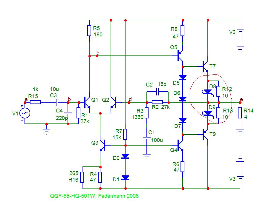
And the D5,D6,D7 bias - wow!
These diodes are excellent, but must be sufficient profit in the high frequencies.
These diodes are excellent, but must be sufficient profit in the high frequencies.
Yes, the 'profit' is very important. We suffered a bit in the year 2009
A DIY forum, ain't that?
But still nothing on topic, which is: Influence of the delay amplifiers for listening characteristics
Please stay on topic, as Mr. Federmann used to say
We discussed the voltage dependence.
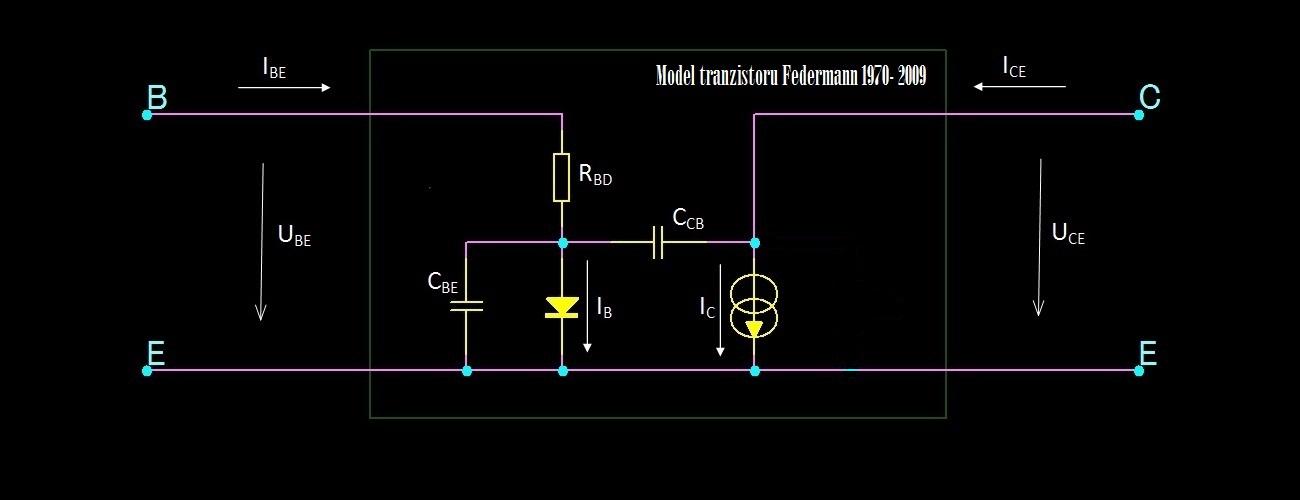
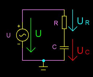
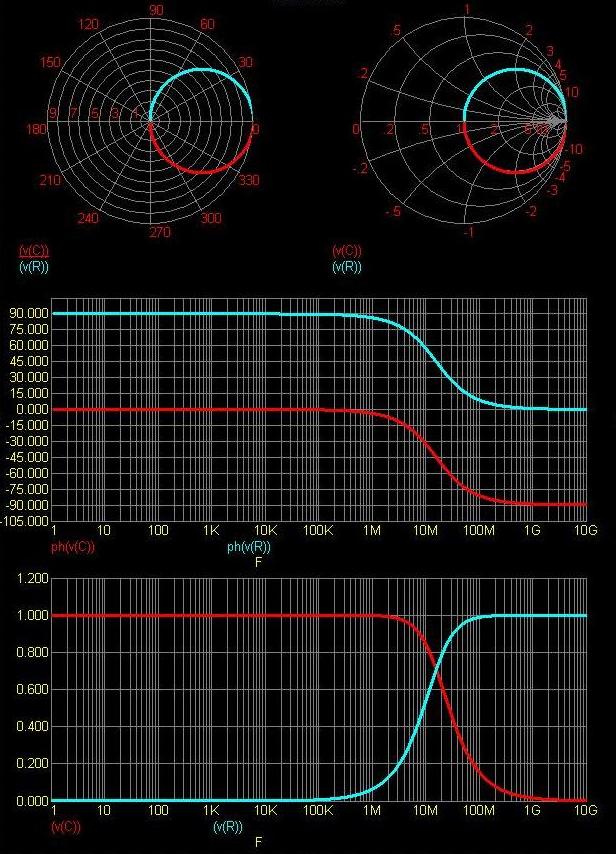
I returned to the original topic. We discuss the frequency dependence.
Me used equivalent circuit of the transistor.
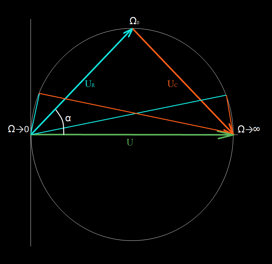
The decrease in gain by 10%. It can be deducted on RC about charts. You can see tension and angle.
For 10% deviation:
Maximum Vdif for a D(transfer) of a BJT LTP is 18mV.
Maximum Vdif for a D(transfer) of a Jfet LTP is 268mV.
The NTP is weird though because there are different margins for positive and negative errors...
10% deviation margin for positive excursions is about 3mV, while for negative is 6.3mV. The NTP is very odd in comparison...
But these are all things I already knew.
And please, if you have nothing to say that will contribute to the discussion, do not say anything.
- keantoken
Restrictions Vdif may be many new findings.
For whom??
Output voltage / Vdif says the minimum profit.
You are right here
Discussions have already said a lot. Restrictions Vdif may be many new findings. Output voltage / Vdif says the minimum profit.
I'm thinking maybe you misunderstood the latter part of my post.
I am interested whether or not the NTP (blue trace) performs better or worse than the LTP in terms of this odd modulation distortion. I am thankful for the help plotting derivatives and such, since even though it is not what I had in mind I've learned some things that will come in handy.
I would like those who haven't/won't contribute anything meaningful to leave. If I want to do my own research on the subject, I want to do it in peace without several arbitrary voices decreasing the S/N ratio. (if Federman is wrong, I will find out myself!)
I'm working on plotting some more solid data...
- keantoken
Phase shift would be an indicator of high THD20, maybe?
Or perhaps phase shift causes fatigue?
So I think the best route right now is to see what correlations there are between phase shift and IMD.
What are the causes of IMD/nonlinear distortions? how do these same causes affect phase shift?
Really not sure what you would find out.
[snip]
When Vdif in the non-linear, there is IMD. [snip][/QUOTE]
Federmann, are you implying that a non-linear Vdiff somehow leads to IMD? There is a connection, but not causal.
If the forward amplifier is non-linear, it will create IMD because of this.
The Vdiff shows the difference between the clean input voltage and the fraction of the output voltage fed back (that's why it is called 'diff' ;). Naturally, if the forward amp is non-linear (creates IMD as well as HD) this will show up in Vdiff, but Vdiff doesn't cause it.
This is the basis for a paper by Baxandall who worked backwards and come to a method to calculate the non-linearity of amp from looking at Vdiff. I'll see if I can find it.
Edit: And please look up phase shift. Your notion that phase shift causes THD is nonsense. Even a perfect amp with 0.000000001%THD WILL have phase shift. You really should understand that these have nothing to do with each other before you can progress with your understanding, otherwise you keep going around in circles going no where.
jd
Last edited:
- Status
- This old topic is closed. If you want to reopen this topic, contact a moderator using the "Report Post" button.
- Home
- Amplifiers
- Solid State
- Influence of the delay amplifiers for listening characteristics