Broken tracks
Hi all,
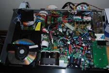
Whats the best way to repair broken PCB tracks. Thought I could get that conductive silver paint but can it be soldered to? The problem is around the diodes.
Also, is there any way to check a diode is ok without powering it up. I'm convinced i've got some duff or fried ones. cheers, Steve
Hi all,
Whats the best way to repair broken PCB tracks. Thought I could get that conductive silver paint but can it be soldered to? The problem is around the diodes.
Also, is there any way to check a diode is ok without powering it up. I'm convinced i've got some duff or fried ones. cheers, Steve
Hi all,
Whats the best way to repair broken PCB tracks. Thought I could get that conductive silver paint but can it be soldered to? The problem is around the diodes.
Also, is there any way to check a diode is ok without powering it up. I'm convinced i've got some duff or fried ones. cheers, Steve
Use a piece of wire as a jumper. Back in my early modding days I had to use this trick due to being clumsy with the board.
To test the diode you can use the diode test that comes as standard on 90% of meters. You'll probably need to remove the diode first. In one direction it should read something like 600mV iirc!
Good luck.
Simon
Thanks for the ideas.
Where can I get a replacement ribbon from?
How do I check the 5V rails?
thanks
Steve
Replacing the ribbon is not necessarily going to help, as it's more likely to be the connectors the ribbon plugs into that are at fault.
To check the 5V rails you need a multi-meter - any will do as they all have a DC voltage test. You connect the black probe to ground (CDP chassis or output RCA shell, for example) and the red probe to a point where you want to measure voltage. There are "fuse" resistors leading to each of the chips and these make potential test points. Maybe someone can remember the resistor circuit board numbers, I can't.
Simon
Just for your info... My CD53 as is right now... I am considering replacing the mega cap for a 10.000uF after the main 5 reg
Once started you can never stop....(Note that I am also scared about possible ribbon issues... pad lifting... erroneous use of DMM tips... etc...) but I just can not stop
With this I mean that one must be really carefull and plan every move with loads of anticipation before going on.
I once nearly killed the machine just by trying to measure the voltages on one of the driver chips with a not very steady hand and without googles on... I killed the servo chip and it took me 1 month without music and lots of worriing posts.
Now I am really carefull
I consider it is a very worthwyle effort because my machine sounds better than a super specked DENON DCD3300 (After playing 3 or more discs... it needs to warm up due to some special caps in use).
So much to do and so little time........
Attachments
Last edited:
broken tracks
Cheers Simon, gonna need it
Use a piece of wire as a jumper. Back in my early modding days I had to use this trick due to being clumsy with the board.
To test the diode you can use the diode test that comes as standard on 90% of meters. You'll probably need to remove the diode first. In one direction it should read something like 600mV iirc!
Good luck.
Simon
Cheers Simon, gonna need it
Just for your info... My CD53 as is right now... I am considering replacing the mega cap for a 10.000uF after the main 5 reg
Once started you can never stop....(Note that I am also scared about possible ribbon issues... pad lifting... erroneous use of DMM tips... etc...) but I just can not stop
With this I mean that one must be really carefull and plan every move with loads of anticipation before going on.
I once nearly killed the machine just by trying to measure the voltages on one of the driver chips with a not very steady hand and without googles on... I killed the servo chip and it took me 1 month without music and lots of worriing posts.
Now I am really carefull
I consider it is a very worthwyle effort because my machine sounds better than a super specked DENON DCD3300 (After playing 3 or more discs... it needs to warm up due to some special caps in use).
So much to do and so little time........
Hehe excellent. Keep marching on
Brent
Have figured out the problem,
I had ruined the connection between the clock input and the DAC now hard wired.
The disc now spins and plays however I get no sound at all. I have just changed the opamps for ad843knz.
Any help appreciated.
Steve
Good news on the dac wiring.
You have fitted the wrong opamps! Single instead of dual
Brent
Hoping this will be useful:
I found at least three ground loop in the schematic of this cdplayer (see images), and also ground traces that intercross (is this the right word?).
Anyway, I'm going to rebuild all the power section and conseguently all the ground design.
Could anyone suggest me a good and cheap diy clock for this player????
I think the Kwack clock is intresting, but I don't have an oscilloscope, so I can't build the version 7.
Can you help me?
WONDERFUL THREAD!!!!
I found at least three ground loop in the schematic of this cdplayer (see images), and also ground traces that intercross (is this the right word?).
An externally hosted image should be here but it was not working when we last tested it.
An externally hosted image should be here but it was not working when we last tested it.
An externally hosted image should be here but it was not working when we last tested it.
Anyway, I'm going to rebuild all the power section and conseguently all the ground design.
Could anyone suggest me a good and cheap diy clock for this player????
I think the Kwack clock is intresting, but I don't have an oscilloscope, so I can't build the version 7.
Can you help me?
WONDERFUL THREAD!!!!
Hoping this will be useful:
I found at least three ground loop in the schematic of this cdplayer (see images), and also ground traces that intercross (is this the right word?).
An externally hosted image should be here but it was not working when we last tested it.An externally hosted image should be here but it was not working when we last tested it.An externally hosted image should be here but it was not working when we last tested it.
Anyway, I'm going to rebuild all the power section and conseguently all the ground design.
Could anyone suggest me a good and cheap diy clock for this player????
I think the Kwack clock is intresting, but I don't have an oscilloscope, so I can't build the version 7.
Can you help me?
WONDERFUL THREAD!!!!
Nice one, people can now see the gnd problems within the 63. Its the reason a few of us have cut tracks and run individual gnd wires to a star gns point.
Brent
Hi GUYS, i am collecting parts for DOS AS PER RAY LIST-problem is getting the exact resistors as i am ordering from PC-eg- 1K8 instead of 1K82-would there be any problem?
No problem at all.
Brent
It would make for a wonderful intermediate stage, before the HDAM.
Is that before the HDAM is bypassed
Brent
Is that before the HDAM is bypassed
Brent
Didn't follow this thread since I don't have these CDPs... I only read one or two posts (and looked @ the pics above)
But it's equally worth trying the LT1028ACN8, HDAM or not...
Didn't follow this thread since I don't have these CDPs... I only read one or two posts (and looked @ the pics above)
But it's equally worth trying the LT1028ACN8, HDAM or not...
Fully agree
Brent
- Home
- Source & Line
- Digital Source
- Marantz CD63 & CD67 mods list