spread sheet
Hey andrew,
Could you give me the link to your air core inductor spreadsheet post?
Thanks,
Steve
+-45mF is not a lot for a ClassA amp that can drive 4ohms into ClassAB.
I posted the air core inductor spreadsheet quite a while ago.
183Turns calculates to 2.0mH and has 0r34 resistance, but it's big. 14.3turns/layer, 12.9layers = 184Turns resulting in 89.2mm diameter and 22.9mm spool width, using 40m of wire.
2mH using 1.9mm wire gives 103mm diameter and uses more than a 1kg spool of wire.
Hey andrew,
Could you give me the link to your air core inductor spreadsheet post?
Thanks,
Steve
Hey andrew,
Could you give me the link to your air core inductor spreadsheet post?
Thanks,
Steve
You can also use our pal "google" to find something similar and perhaps even easier than the spreadsheet:
Pronine Electronics Design - Multilayer Air Core Inductor Calculator
There are plenty more calculators out here - search for "multilayer air core inductor calculator"
see post 4239
Hi Bobo,
I am not referring to +- 24 but +48VDC-0VDC into F5 circuit.Will it work?
+-45mF is not a lot for a ClassA amp that can drive 4ohms into ClassAB.
I posted the air core inductor spreadsheet quite a while ago.
183Turns calculates to 2.0mH and has 0r34 resistance, but it's big. 14.3turns/layer, 12.9layers = 184Turns resulting in 89.2mm diameter and 22.9mm spool width, using 40m of wire.
2mH using 1.9mm wire gives 103mm diameter and uses more than a 1kg spool of wire.
Will this do for the lazy ones? ERSE-XQ
Hi Bobo,
I am not referring to +- 24 but +48VDC-0VDC into F5 circuit.Will it work?
I fear not to understand exactly what you mean.
Will this do for the lazy ones? ERSE-XQ
I would be suspicious looking at the price. At that cost, it is unlikely to be respectable quality magnet wire, that it's made of.
For a cross-over, I wouldn't hesitate using that sort of questionable quality, as the power involved is a fraction of that in the CLC filter.
Magura
")
Choke versus resistor PS filter
Excuse me for asking this question again but the first time no on offered an explanation and with the renewed interest in replacing the resistors with a choke ...
Using the DUNCAN AMP PSU tool when I replace the resistor with a choke (with the sames DCR, inductance doesn't seem to make that much difference with values available) I get much higher ripple. Not slightly higher, order of magnitude higher.
As others have said, using chokes is standard procedure with tube gear and I have used them in tube projects, also.
Can one of the more enlightened enlighten me? I suspect a few others would enjoy the explanation, also.
THANKS,
if I were designing a CLC for an F5, I would use 6m8F//6m8F//6m8F as the first capacitor bank, then 180turns of 1.6mm diameter enameled copper on a 48mm air core former (700gms of copper) and then 15mF//15mF//15mF as the second stage capacitor bank.
Here's a simulation of a 2mH choke and a 200uH choke -- switching the load between 1A and 3.3A -- 800uS/200uS
Attachments
Hi
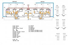
Here is my new F5 layout with triple outputs
I do have both PDs and CVs F5 boards, and looking at them has helped me some
Still, I like a challenge
Do you think this will work ok
Or is there somethindg that needs changed
btw, Amplimo makes 2x18V, 2x20V, 2x22V trafos
Here is my new F5 layout with triple outputs
I do have both PDs and CVs F5 boards, and looking at them has helped me some
Still, I like a challenge
Do you think this will work ok
Or is there somethindg that needs changed
btw, Amplimo makes 2x18V, 2x20V, 2x22V trafos
Attachments

Last edited:
Hi
Here is my new F5 layout with triple outputs
I do have both PDs and CVs F5 boards, and looking at them has helped me some
Still, I like a challenge
Layout
Layout
Yeah, it slipped but corrected
Please just give your honest opinion
No need to be gentle on me, even if its my first

btw, its supposed to be a hybrid/semi hardwired build
Attachments
Last edited:
Could be, I am still trying to find the ideal.
I did my setup with 2 pairs of outputs per F5 channel. I was hoping to bias them at about 1 amp per device, but I ended up at about .8 amps per device before my rail voltage sagged too much - my goal was to stay in Class A throughout the useful range of my highly reactive, less than 4 ohm speakers and get the damping factor up as well. I ended up having the power supply voltage drop a bit as I raised the bias, effectively bringing my power potential down. I had to piggyback a couple more resistors in the power supplies to get the voltage back up a bit, and added some more capacitance to get keep the ripple down, but I ended up with +/- 18 volts instead of +/-24 at the rails. This is with 18-0-18 400va toroid.
I am going to get a higher power transformer and try to get the rails back up to +-22 (or 24) volts and then try again. This is a lot of heat to deal with as well. With the stock value of 1.2 amps per device and a total of 4 devices, everything runs pretty cool compared to 8 devices at .8 amps. with everything biased higher I have to have forced air blowing over the large finned rectifier heatsink to keep it below 70c.
For testing I have one channel set up with .6 amps across each device and one channel with 1 amp across each device trying to see if I can tell a difference in any musical situation. So far I can't tell a difference, but I think that my weakest link is not the amplifier.
Both channels measure well with the measuring software/hardware I have. They have not ever tested identically though.
Hi
Here is my new F5 layout with triple outputs
I do have both PDs and CVs F5 boards, and looking at them has helped me some
Still, I like a challenge
Do you think this will work ok
Or is there somethindg that needs changed
btw, Amplimo makes 2x18V, 2x20V, 2x22V trafos
I have already done this, see post number #5047 on page 505.
It ran extemely well. You shouldn't have any problems what so ever.
As a comparison it performed significantly better than a Naim amp.
Last edited:
Really not a problem. Just match them up a bit, increase
the Source resistance, and go to town.
Occasionally you will have to think about compensation,
but a cap on the feedback loop resistor will pretty much
take care of it.
Nice respond from Nelson upon my question about multiple outputs
Well, I have some not so clever questions
1. Well, which is source resistor ?
2. And raise value by how much ?
3. Cap on feedback loop resistor, which is that ?
How big a cap ?
4. Power resistors 5,6,7,8, from input to output
They are double 100ohm, is that because they need to be 6watt or just
fore adjustment of value ?
5. Power resistors between supply line and power transistors
Why only 3watt resistors ?
Attachments

- Home
- Amplifiers
- Pass Labs
- F5 power amplifier