Chokes
Hey Magura,
Being that this is a push-pull amp, you really don't have constant current draw during class A either. Of course it is at lower current than when you drive her into AB.
I am curious to see if CRC might just be better than CLC for this amp.
Thanks,
Steve
Hey Magura,
Being that this is a push-pull amp, you really don't have constant current draw during class A either. Of course it is at lower current than when you drive her into AB.
I am curious to see if CRC might just be better than CLC for this amp.
Thanks,
Steve
Just an update regarding switch mode power supply noise.
I was able to find some equipment (FLUKE) that could measure noise down to 20uV.
Here are the results.
The noise from the switch mode supply before passive filtering was 8.58mV pk-pk, and after passive filtering was 783uV pk-pk (or 0.783mV pk-pk)
I was able to find some equipment (FLUKE) that could measure noise down to 20uV.
Here are the results.
The noise from the switch mode supply before passive filtering was 8.58mV pk-pk, and after passive filtering was 783uV pk-pk (or 0.783mV pk-pk)
Just an update regarding switch mode power supply noise.
I was able to find some equipment (FLUKE) that could measure noise down to 20uV.
Here are the results.
The noise from the switch mode supply before passive filtering was 8.58mV pk-pk, and after passive filtering was 783uV pk-pk (or 0.783mV pk-pk)
What bandwidth?,
Noise measurement, without specifying bandwidth, is of little to no utility.
What type of detector on the Fluke?
True RMS detectors/converters vary greatly in their accuracy.
Did you look at it with a scope to see the periodicity?
Measuring on a meter or DMM tells you a little, but looking at the spiky's on an SMPS power supply output tells you a lot more on how they will interfere with sensitive audio circuitry. It's not just the noise in the audible bandwidth, it's the magnitude and frequency of the spikes which can get rectified by every nearby PN junction.
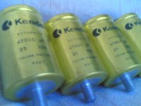
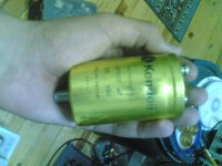
hi..i have 8 pieces of italy made 25volts 47000uf kendeil capacitors and 0-18 0-18 0-18 0-18 toroidal transformer.. what kind of power supply should i design?what is the most reliable power supply for using with F5 amp?dual monoblocks or other types? how many bridge diodes should i use ? i will take photos and send asap.. thanks
Attachments
Last edited:
Did you look at it with a scope to see the periodicity?
Maybe you should look at post #5186 on page 519
Sorry, posted while I was in the UK -- try a bit of inductance on the output -- and make sure the input to the SMPS is filtered as well.Maybe you should look at post #5186 on page 519
It doesn't really matter that the noise pulse is outside the audio band as there are 2 problems -- one as I cited is the excitation of PN junctions by power supply noise -- this leads to offset and distortion. The second is the mixing of the audio signal with RF which produces sidebands.
The Tangent LN amplifier would benefit from some input protection -- some low leakage diodes on the front end and some RCL filtering of its own...
do you have a pcb for f5?hi..i have 8 pieces of italy made 25volts 47000uf kendeil capacitors and 0-18 0-18 0-18 0-18 toroidal transformer.. what kind of power supply should i design?what is the most reliable power supply for using with F5 amp?dual monoblocks or other types? how many bridge diodes should i use ? i will take photos and send asap.. thanks
hi huseyin how are you..i wish you will draw a good pcb for us and we will group buy...
There are already 3 designs available, so unless you want to do it for the experience, I doubt there will be much action in such a gb.
Cviller: http://www.diyaudio.com/forums/group-buys/134554-gb-f5-pcb.html
Peter Daniel: http://www.diyaudio.com/forums/group-buys/140306-f5-pcb-group-buy.html
suds: http://www.diyaudio.com/forums/group-buys/144908-firstwatt-f3-f5-clone-gb.html
.....
Can I know if I can feed F5 with +48v and 0v (gnd), will it work? no?
yeah - with so-called Quad arrangement of PSU
see what bobodioulasso wrote
if I were designing a CLC for an F5, I would use 6m8F//6m8F//6m8F as the first capacitor bank, then 180turns of 1.6mm diameter enameled copper on a 48mm air core former (700gms of copper) and then 15mF//15mF//15mF as the second stage capacitor bank.
Your two channels will require a minimum of 250mF and 3.1kg of copper. That is an expensive PSU. It will work for both the ClassA operation (1.3A bias) and for the ClassAB operation.
It will even work with a ClassAB amplifier (150W into 8r0) irrespective of the output stage bias.
Your two channels will require a minimum of 250mF and 3.1kg of copper. That is an expensive PSU. It will work for both the ClassA operation (1.3A bias) and for the ClassAB operation.
It will even work with a ClassAB amplifier (150W into 8r0) irrespective of the output stage bias.
if I were designing a CLC for an F5, I would use 6m8F//6m8F//6m8F as the first capacitor bank, then 180turns of 1.6mm diameter enameled copper on a 48mm air core former (700gms of copper) and then 15mF//15mF//15mF as the second stage capacitor bank.
Your two channels will require a minimum of 250mF and 3.1kg of copper. That is an expensive PSU. It will work for both the ClassA operation (1.3A bias) and for the ClassAB operation.
It will even work with a ClassAB amplifier (150W into 8r0) irrespective of the output stage bias.
Hi AndrewT,
2 questions:
1. Is there a reason why you need so much more capacitance for a CLC as compared with a CRC?
2. In your example: "180turns of 1.6mm diameter enameled copper on a 48mm air core former " -- how many Henries does that come out to?
Thanks,
Steve
how to calculate the most reliable power supply?
hi Andrew..i dont know how to calculate the most reliable power supply for F5 amp..i have these materials
1-) 0-18 0-18 0-18 0-18 600VA toroidal transformer
2-)8x 25volts 47mf kendeil capacitors
3-)0.47 ohm 3watts dale resistors
would you say how to make the best supply and best noise reduction and how many resistors should i connect paralleled for it?thank you
Last edited:
+-45mF is not a lot for a ClassA amp that can drive 4ohms into ClassAB.1. Is there a reason why you need so much more capacitance for a CLC as compared with a CRC?
2. In your example: "180turns of 1.6mm diameter enameled copper on a 48mm air core former " -- how many Henries does that come out to?
I posted the air core inductor spreadsheet quite a while ago.
183Turns calculates to 2.0mH and has 0r34 resistance, but it's big. 14.3turns/layer, 12.9layers = 184Turns resulting in 89.2mm diameter and 22.9mm spool width, using 40m of wire.
2mH using 1.9mm wire gives 103mm diameter and uses more than a 1kg spool of wire.
Last edited:
I just completed my F5. The value of resistor is according to reference on the passdiy web. However, when I adjusted the bias and output DC, I adjusted P1 and P2 to keep voltage of R11 around 0.6V. I noticed the value was changed all the time. It can't be fixed in a value. The output DC is in the same situation. What's wrong?
- Home
- Amplifiers
- Pass Labs
- F5 power amplifier