Thank you Dr. Geddes for you clarification and for the recommendation.
I belive my statement was not very clear. I think you can confirm this: my understanding was that in designing an OS profile, loading is not needed to be taken into account. The other profiles however, are using loading in the equations needed to describe the profile.
That's not entirely correct either. Basically, I don't believe that loading is important at all, so it was ignored in all my publications and derivations. People took that to mean that the loading was not very good, which is entirely untrue. I later showed that if you use Websters Equation on the OS profile that you get almost exactly the same loading for the same areas of input and output as you do for an Exponential, etc. Loading depends on wall angle, which is just another way of expressing flare rate. So, as far as loading is concerned, there is no difference in the profiles and as I showed in my paper in AudioExpress, loading has only a very minimal effect on response for any contour. All in all loading is a totally over blown concept that should just go away.
People in the p.a. business tell me that when they started to use c.d. horns they started blowing out compression driver diaphrams with the same power inputs that were used with exponential horns.
Upon investigating this they discovered that the new c.d. horns had an extended complex impedance at the lower end that caused excesive diaphram excursions, and that the rapid onset of resistive loading in the exponential device is a desirable attribute because of this.
rcw.
Upon investigating this they discovered that the new c.d. horns had an extended complex impedance at the lower end that caused excesive diaphram excursions, and that the rapid onset of resistive loading in the exponential device is a desirable attribute because of this.
rcw.
People in the p.a. business tell me that when they started to use c.d. horns they started blowing out compression driver diaphrams with the same power inputs that were used with exponential horns.
Upon investigating this they discovered that the new c.d. horns had an extended complex impedance at the lower end that caused excesive diaphram excursions, and that the rapid onset of resistive loading in the exponential device is a desirable attribute because of this.
rcw.
Sorry, but I don't believe this.
Thank you for your reply, much appreciated. I will dig into your article for further details.
So, as I understand, loading has nothing to do with the length of the horn? Just with the flare rate?
Horn length will affect the impedance seen by the horn because of standing wave reflections. But the mean level of the impedance is purely related to the flare rate.
Hello,
The troat impedance of "classical" OS waveguide (12" or 15" mouth diameter, 45° to 90°) is quite similar to the throat impedance of horns (hypex or exponential) having a very high cut-off frequency (more than 1kHz).
The resistive part of that impedance of those OS waveguide shows dips and peaks and is nothing constant (more than 50% variations).
By comparison the thoat impedance of a Le Cleac'h horn is quasi purely resistive and very constant (variation lesser than 5%) for frequency above the cut-off frequency (> 2. Fc). And we should remember that the Fc of the Le Cleac'h horn (as estimated from the impedance curve) can be far lesser than 1kHz...
Best regards from Paris, France
Jean-Michel Le Cléac'h
Jean-Michel Le Cléac'h
Another consideration on my site about driver resonnance frequency and cut-off frequency of horn:
http://thend.chez-alice.fr/Appendix/Appendix2.html
http://thend.chez-alice.fr/Appendix/Appendix2.html
Hello,
The resistive part of that impedance of those OS waveguide shows dips and peaks and is nothing constant (more than 50% variations).
Jean-Michel Le Cléac'h
This is simply not true if the waveguide is properly designed with a large mouth flare. I should have hoped that you would know that.
This is simply not true if the waveguide is properly designed with a large mouth flare. I should have hoped that you would know that.
Do you have an impedance plot you will share for your largest horn?
Thend - what are you calling Fs? Is it the resonant frequency of the driver with no horn or tube attached? That often shows as 2 large peaks, the Fs being in between those two.
And I assume that Fa is the cut-off freq. of the horn? How is that determined? Sorry for the questions (un peu bete) but just want to make sure of what you are doing - what the terms mean.
And I assume that Fa is the cut-off freq. of the horn? How is that determined? Sorry for the questions (un peu bete) but just want to make sure of what you are doing - what the terms mean.
Hello Earl,
I have under my eyes throat impedance curves (resistive and reactive part) for both a large OS waveguide (similar to the one in your Summa I guess) with a curved mouth radius according to your recommendation and the same for a Le Cléac'h horn (AH425 in that case).
Above 800Hz for the Le Cléac'h horn (Fc = 425Hz) the resistive part of the throat impedance varies very smoothly between 0,95 and 1,05 and the reactive part of the impedance is lesser than 0.05 and never take negative values.
Above 1200 Hz for the OS waveguide the resistive part of the impedance varies between 0.3 and 2.65 with many peaks and dips and the reactive part of the impedance varies between +2.4 and -1.4 (with peaks and dips...)
Adding a foam plug should smooth a bit the throat impedance curves of the OS waveguide over 3kHz but will be not so effective under 3kHz as it seems from measurements you published. The peaks between 1200Hz and 2000Hz on the curve of the resistive part of the impedance will not be cured and in the same interval of frequency the peak followed by a hole on the curve showing the reactive part of the impedance will not be cured either.
Best regards from Paris, France
Jean-Michel Le Cléac'h
P.S. I am not allowed to publish the curves but you probbaly know their source.
This is simply not true if the waveguide is properly designed with a large mouth flare. I should have hoped that you would know that.
Last edited:
Do you have an impedance plot you will share for your largest horn?
Do you mean driver impedance, or waveguide impedance? Driver impedance is an easy electrical measurement, but then you have to sort out what's the driver resonances from the waveguide. This makes comparing curve impossible unless they both use the same driver.
If you mean a direct measurement of the waveguide impedance that's a very difficult measurement that I don't think many have ever done, although I have (see my AES paper from some 20 years ago).
Jean-Michel
As usual you are comparing apples to oranges as those two devices are not comparable. And if those are simulations then that is a question as well. The fact is that if there is no mouth reflection the real part of the impedance of any device with the same throat size will be identical. I would hope that you rewalize this. So if there is an aberation then there is a reflection, and if there is a reflection then the mouth is not large enough with an inadequite flare.
As usual you are comparing apples to oranges as those two devices are not comparable. And if those are simulations then that is a question as well. The fact is that if there is no mouth reflection the real part of the impedance of any device with the same throat size will be identical. I would hope that you rewalize this. So if there is an aberation then there is a reflection, and if there is a reflection then the mouth is not large enough with an inadequite flare.
Thend - what are you calling Fs? Is it the resonant frequency of the driver with no horn or tube attached? That often shows as 2 large peaks, the Fs being in between those two.
Fs is just only the resonant frequency of driver, just the mass-spring system that is not really visible in the case of compression driver (cavity).
And I assume that Fa is the cut-off freq. of the horn?
Yes:
We note also, the horn reduces the amount of energy which returns in the approach of its acoustic cut-off frequency (Fa) as explained on its page of origin.
In view of this two documents, we can conclude that the acoustic energy returned by the horn can be absorbed by the compression driver at its resonant frequency (Fs).
I'm trying to search something more clear, idea?
How is that determined?
By conception (I'm not specialist), by manufacturer documents or by measure.
But instead of get an Fa depending Fs, maybe we get a Fs depending Fa by changing the rear closed volume like a closed box and its Fc.
I only have BMS driver and it's not possible with it.
Last edited:
Hello Earl,
The mentionned OS waveguide has the curved mouth you recommanded.
This rounded mouth you recommanded appears to not be efficient to reduce drastically reflection of waves at the mouth.
Even if a round mouth could solve that problem, the throat impedance of the OS waveguide will still be at best comparable to the impedance of a short hypex horn calculated for a tweeter.
A Le Cléac'h horn of the same size will bring to the driver a perfect acoustic load at a frequency 3 times lesser and this is quite well reflected in the measurements (e.g. waterfall).
Best regards from Paris, France
Jean-Michel Le Cléac'h
Jean-Michel
As usual you are comparing apples to oranges as those two devices are not comparable. And if those are simulations then that is a question as well. The fact is that if there is no mouth reflection the real part of the impedance of any device with the same throat size will be identical. I would hope that you rewalize this. So if there is an aberation then there is a reflection, and if there is a reflection then the mouth is not large enough with an inadequite flare.
But instead of get an Fa depending Fs, maybe we get a Fs depending Fa by changing the rear closed volume.....
Hmmmm......, Hmmmm.... Yes maybe. But how to know what is Fs? Electrical measurement? Below is a graph of an Altec 291-16K driver in free air (2 peaks) and on an Altec 803B horn (1 peak).
I believe the Fa of this horn is about 130Hz. It's meant for use down to 300 Hz. Would be interesting to see what a larger rear chamber does to the impedance curve.
Attachments
Hello Earl,
A Le Cléac'h horn of the same size will bring to the driver a perfect acoustic load at a frequency 3 times lesser and this is quite well reflected in the measurements (e.g. waterfall).
Best regards from Paris, France
Jean-Michel Le Cléac'h
Again, an apples and oranges comparison of no relavence. Loading is unimportant, but directivity is. Your horns have been shown to be very poor for the more important criteria - directivity. It matters not how the impedances compare.
Loading does effect CSD characteristics. How can we quantify what is more important?Again, an apples and oranges comparison of no relavence. Loading is unimportant, but directivity is. Your horns have been shown to be very poor for the more important criteria - directivity. It matters not how the impedances compare.

Hmmmm......, Hmmmm.... Yes maybe. But how to know what is Fs? Electrical measurement?
Precisely on that page, I shows 2 differents ways to know Fs.
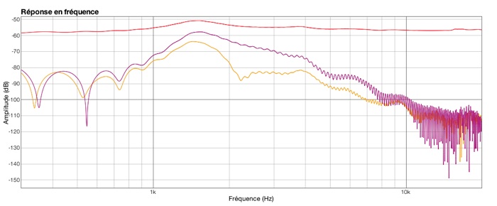
An acoustical, see the green curve:
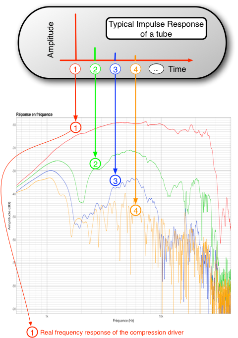
And an electrical, the maximmum of energy captured (absorbed) in the first echo (purple and orange) corresponds to Fs.
Note: This BMS have one peak at Fs (red, pure impedance curve with 1 meter tube long).
For more detail, see the rest of my site.
Below is a graph of an Altec 291-16K driver in free air (2 peaks) and on an Altec 803B horn (1 peak).
I believe the Fa of this horn is about 130Hz. It's meant for use down to 300 Hz. Would be interesting to see what a larger rear chamber does to the impedance curve.
I dont know, maybe the "free air" Fs of this driver is above Fa anyway.
And a classical compression driver which can reproduce the 130hz without ditortions, I do not really believe.
To measure impedance, it's better with tube for discriminate the reflection of the driver mouth.
- Home
- Loudspeakers
- Multi-Way
- Jean Michel on LeCleac'h horns