tiki said:Hello,
thanks for the simulations. One should differ between horizontal and vertical directivity/sonograms, but you did, I'm sure.
The lobing effect and its influence on the amplitude response is already described in the well-known Ureda paper "Line Arrays: Theory and Applications". I am convinced that the LA has major advantages over a point source anyhow. Normally I cannot hear the "gaps" while playing music, although they are measurable.
Regards, Timo
Sure
")
to be less confusing
"The sound field distribution of your WG seem to be still pretty closely related to the "christmas tree / pagoda" pattern...."
I should have better put :
"The directivity sonogram of your WG seem to be still pretty closely related to the "christmas tree / pagoda" pattern"
In any case - I did a short introduction on "how to decipher" directivity sonogram in:
http://www.diyaudio.com/forums/show...195#post1888195
Michael
This is another 3k waveguide sim, the same device as the first.
Now however it is on a 185mm. wide baffle 200mm. deep, simulating a real enclosure in front of a wall...
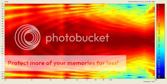
The diffraction field due to the finite baffle presence gives quite a diiferent result from an infinite baffle and explains why the waveguide measures better above 10k. than the infinite baffle sim shows.
rcw.
Now however it is on a 185mm. wide baffle 200mm. deep, simulating a real enclosure in front of a wall...
The diffraction field due to the finite baffle presence gives quite a diiferent result from an infinite baffle and explains why the waveguide measures better above 10k. than the infinite baffle sim shows.
rcw.
rcw said:This is another 3k waveguide sim, the same device as the first.
Now however it is on a 185mm. wide baffle 200mm. deep, simulating a real enclosure in front of a wall...
The diffraction field due to the finite baffle presence gives quite a diiferent result from an infinite baffle and explains why the waveguide measures better above 10k. than the infinite baffle sim shows.
rcw.
interesing that you use AxiDriver to simulate room effects from bookshelf placememt.
To which of the simus before actully is this one related
posting #456 or #458
l
Michael.
rcw said:This is the same device as the 456 posting, notice the center minimum at around 18kHz. where a second Fresnel zone is in the aperture.
rcw.
What is most obvious to me - the trumpet below - say 4kHz - turns towards the "whale's head" - same as in my simus of infinite baffles versus bending back the horn contour (360 deg "included" angle).
As for the rest - to me its hard to say if the widespread "fresnell defects" are more desirable than some single , more "solid" defects in the sound field.
Tiki told us that he is not bothered by the "bones" of his line array - so might be if the defects in the sound field are "of a closely spaced pattern", they are not as harmful as it looks like from simus / measurements...
Michael
A word of caution here. Much of what you are seeing in the sims is due to "spatial aliasing" and not a real effect. To demonstrate this to yourself, run a sim of a piston source with very high resolution and plot it in exactly the same way that you are showing here. You will see that ALL of the diffraction line go as curves with centers located at higher frequencies and angles. Never do we see anything else. When you lower the resolution you wil begin to see the curves go in other directions - like spokes on a wheel in a film. This is aliasing that results from too low of a spatial resolution. I take about this in both of my books.
Thanks for pointing out a possible pitfall.
Could you please be more specific – any pictures of mine so far where aliasing effects possibly have compromised my simus shown?
If not – please post an example how such aliasing-effects will look like.
If so - please show which ones and to what extend.
Michael
Could you please be more specific – any pictures of mine so far where aliasing effects possibly have compromised my simus shown?
If not – please post an example how such aliasing-effects will look like.
If so - please show which ones and to what extend.
Michael
The usual procedure for testing sims is to increase the resolution, usually double and note any changes. If there are any then you need to keep increasing the resolution until the changes cease. Usually the changes will stop at low wavenumbers first and you will then be able to see where the aliasing states and where you data is valid and where it is not. If you cannot double the resolution then half it. If the picture changes then you have a big problem because you are into a region for which your simulation cannot hold enough accuracy and you have to discard the whole approach.
What you are going to find is that you can get reasonable accuracy at low wavenumbers, but at the higher wavenumbers this will not be possible. Thats why I went to an analytical approach, to get to wavenumbers which were high enough to be useful. The sims of my day were not capable of going to anywhere near high enough wavenumber to be useful.
What you are going to find is that you can get reasonable accuracy at low wavenumbers, but at the higher wavenumbers this will not be possible. Thats why I went to an analytical approach, to get to wavenumbers which were high enough to be useful. The sims of my day were not capable of going to anywhere near high enough wavenumber to be useful.
Ok,
- some time back when I asked the developers of AxiDriver about details of their "auto meshing" function I got the response that there have had been problems in the past that have been solved now (well isn't everybody expecting such answers?)
I was suspicious at first too - but given the very different directivity sonogram patterns at the top end of direct radiators, your OS, the LeCleach contour and Tikis line source reconstruction I gained some faith in what we got from my simus so far.
Good to hear that you haven't seen aliasing in my simus in particular - I'll keep an eye on it...
What I too have experienced is that the resolution of the geometry imported into AxiDriver sometimes has to be pretty high.
This pushes the number of nodes that have to be calculated and unfortunately slows further down speed.
It seems to be highly dependant on the contour and its sensitivity to mismatch in certain areas.
All in all its a little bit of an balancing act – but hey, what isn't in life and audio –
I appreciate fair criticism of what I show anytime!
Michael
Hello,
Regards, Timo
Although you might see similar structures, the usual reason for this does not exist: there is only one sound source. The "beaming" above 9kHz arises due to the 31mm wide magnetostat front opening. The narrow dips an peaks may result from the regular hole structures (for woofers behind) and from the far-from-optimum curvature of the WG. Please do not jumble the things."The directivity sonogram of your WG seem to be still pretty closely related to the "christmas tree / pagoda" pattern"
Regards, Timo
Michael,
Care to show us the OS version *with* roundover into the baffle? Otherwise this again is sort of unfair.
And please normalize the directivity plots to the 0° on-axis SPL (only a few mouse clicks away, "normalize --> to curve in x-graph"). EDIT: Then again, we know that 0° not necessarily is the optimum angle, for OS....
- Klaus
Took some time – but here we go...
OS of 90 deg included angle and no round over to infinite baffles as already posted:


Same OS of 90 deg included angle with a 50mm / 2" round over to infinite baffles:


Same OS of 90 deg included angle with a 100mm / 4" round over to infinite baffles:


Same OS of 90 deg included angle with a 200mm / 8" round over to infinite baffles:


As can be seen - Earls mantra "the smooth diffraction of OS at the horns' throat is what's really counts" also does not hold.
It's always the whole contour of a horn that contributes to good results – basically we have to look at good alignment of diffraction rather than after avoiding diffraction (which would be "hunting windmills" anyway).
I'll possibly come back to that in more detail in a paper about "alignment of diffraction" I'm working on.
Michael
I don't have very good knowledge of pressure nonliniarities, and so on but, I was just wondering:
Many describe speakers without smooth roundovers to sound colored. Now this has been attributed to diffraction effects.
What I see in the pressure graphs is that roundovers, or lack of them, actually affects directivity?
Many describe speakers without smooth roundovers to sound colored. Now this has been attributed to diffraction effects.
What I see in the pressure graphs is that roundovers, or lack of them, actually affects directivity?
Michael
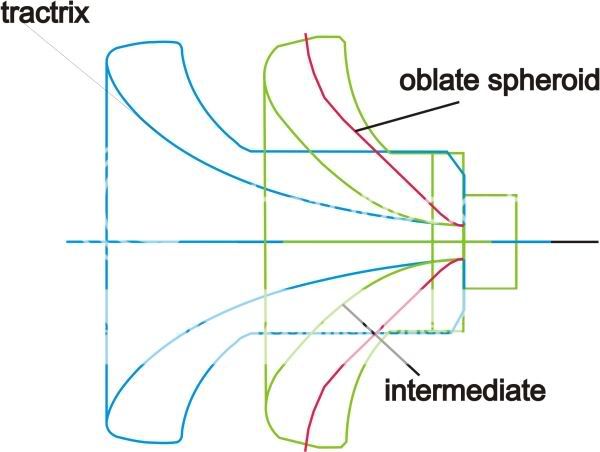
wow. very interesting results !! how about, if the radius at the throat would be bigger ?
Hello Angelo,
Why do you think an intermediate profile would be desirable? It regards the loading of the diaphragm?
Hello Angelo,
Why do you think an intermediate profile would be desirable? It regards the loading of the diaphragm?
yes. exactly. It would also be a smoother, less radical opening transition. I don't know however, if this would be a positive influence.
Last edited:
Angelo, I never had the time to read any theoretical papers on diaphragm loading. I know LeCleach and tractrix are considering loading, OS profiles don't. Can you recommend me some readings?
First, that statement about OS loading is incorrect. OS loads the same as any other contour when the parameters are set correctly. In the drawings shown they will be dramatically different because they do not have comparable flare rates.
I would, of course, recommend my book, Chapter 6, which is all about horns and waveguides and is the most complete discussion that I know of.
Thank you Dr. Geddes for you clarification and for the recommendation.
I belive my statement was not very clear. I think you can confirm this: my understanding was that in designing an OS profile, loading is not needed to be taken into account. The other profiles however, are using loading in the equations needed to describe the profile.
I belive my statement was not very clear. I think you can confirm this: my understanding was that in designing an OS profile, loading is not needed to be taken into account. The other profiles however, are using loading in the equations needed to describe the profile.
- Home
- Loudspeakers
- Multi-Way
- Jean Michel on LeCleac'h horns