Check this Simon's how to for where to check:
I wouldn't do it like that again, I only put regs in directly now as it's neater and better. Next time I work on Steve's I'll take a photo.
Simon
You misunderstand me (again, I may not handle english that well); I meant the player has improved more than what I tought buy judging it with new records and on CDR. The changes were more obvious with pressed CDs I know for years, e.g. The Almighty "Powertrippin" has the clearer bass I've heard on my CDPs, which means it's better than if it was worst or at the same level.
I guess pressed CDs help the sound a bit, I find, without having burnt CDs I own to compare, that the player gets more from a real CD.
Should try with SHM-CD and Gold like MFSL ones.
And as the regulated drivers should add to that my player will be a very good deal... at least I have to convince me")
No, I understood, just having a little joke with you. What we call in England a "play on words".
Your english is 1000x better than my French.
Pete
Has any one seen these players before thay look like merrantz 67 boards http://www.phonosophie.co.uk/here is the link if you want to look
Has any one seen these players before thay look like merrantz 67 boards http://www.phonosophie.co.uk/here is the link if you want to look
Nope. Looks nice though and will no doubt be full of crap parts
Brent
Has any one seen these players before thay look like merrantz 67 boards http://www.phonosophie.co.uk/here is the link if you want to look
Links not working!
So even their top player is just a CD67 with the output stage replaced and an enormous PSU?
The PDFs have the innards:
http://www.phonosophie.de/International/Downloads/PB_IMPULS3_EN_S.pdf
The PDFs have the innards:
http://www.phonosophie.de/International/Downloads/PB_IMPULS3_EN_S.pdf
I wouldn't do it like that again, I only put regs in directly now as it's neater and better. Next time I work on Steve's I'll take a photo.
Simon
Yep Simon, but your way is the easiest for a newbie. I also went on with a very easy direct fit (where my grnd and V+ are from a dedicated PSU but may be replaced just by a single wire from U237, http://img29.imageshack.us/img29/7701/dsc00135l.jpg )
Ahah you just proven I did not caught all your englishNo, I understood, just having a little joke with you. What we call in England a "play on words".
Pete
And yep we say the same, " jeu de mots "! =)And for that High-End product it reminds me the Audio Agile's early cdp, http://www.audiocar.pl/system-cas/tuning/jocker/jocker.htm
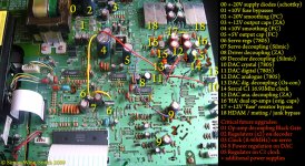
As far as I can see and as few as I know, seems they bypassed the HDAM with their active black box, you can see wihte wires going to caps parts or this is just a kind of "active" capacitor...
No clock, op amp... anyone knows?
It just shows how much business is more of style, image, social posture and bla bla bla than real stuff.
And the link to pdf is for the top one, the 3000€ one is... the small one! These guys are not in prison??
Back to Rush's 2112 on my 150€ CD-53... that rocks!!!
Last edited:
Pants! I've not had any emails from DIY for nearly 2 days and all these posts have been going on AARRGGGHHHH!
Brent
Same here Brent, it sucks. My subscription seems o.k.
Ray
Just to check i take the feed from under C803 remove RD01/RD04 and U200 and feed each with an output from a reg..
Where is best for GND?
Cheers Ian
Perhaps the easiest way to tap ground is by using a fibreglass pencil to scratch the top of the pcb away and solder straight to that.
I fed the 5V regulators in Steve's player from the +11V rail. This is the one that feeds the original 7805. I did this because it's easy, not because it's necessarily best. We plan to feed at least some of them from an additional psu at a later stage (when all the nice and easy mods are done).
I think you'll be fine with C803, as from memory that is the +20V rail.
RD01-RD04 sounds correct. Have you checked those spots measure +5V as standard using a meter? It's good practice to check even if someone says it's ok.
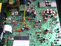
Attaching a pic of Steve's player as modified by myself in 3 stages.
Simon
Attachments
Hi Simon
Thanks for the reply, i have checked RD01/04 and U200 all +5v.
Looking at the pic of Steve's player it looks like you have taken feed from U236 (just behind C813) The voltage there is +12v
I dont have a fibreglass pencil so was thinking i could use the solder blob U275 its located in the defunked headphone section.
Looking at the pic of Steve's player it looks like you have taken feed from U236 (just behind C813) The voltage there is +12v
I dont have a fibreglass pencil so was thinking i could use the solder blob U275 its located in the defunked headphone section.
Yes, that voltage is 12V. I may label it 10V as that's what the service manual calls it.
Using a solder blob (U275 should do - just check it has 0ohms / continuity with the output sockets to be safe) for your regulator grounding will work just fine.
Simon
- Home
- Source & Line
- Digital Source
- Marantz CD63 & CD67 mods list