budget minded said:i'm in eugene and plan on using the amps for a bike system. for some reason, every time i say bike no matter what i'm talking about, everyone always asks "motorcycle?"
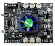
i'm giving serious consideration to the sures then. i love the look of the black SYMMETRICAL motherboard with blue capacitors (?) as i plan on mounting it under plexiglass with LED or cold cathode lighting. i might go the UV route too as i was looking into LED PC fans for a tail light, but translucent hot pink sounds better and would look cool on the black & blue amp.
i'd rather use the screw connectors as the wires will be going straight to to speakers and the banana plugs would get in the way of the 80mm exhaust fan i'm planning on. from what i understand, i could wire it directly into the amp's 5v mute terminals without needing another set of batteries just for the fan. is that correct? i'd rather undervolt a fan for quieter operation anyways.
i'd like to run it with 24v of li-on batteries as that would mean i could use 4 x 3v per side underneath lightweight 92dB pyle outdoor speakers. i'm thinking of putting the batteries under plexi too and probably adding some blue EL wire stripes between the speakers and batteries.
if you're interested, i still have pics of my 1st bike system as well as the unfinished 500w trailer i can't use because i can't get it out my door at my bike system website
http://takatomon2000.googlepages.com/my_street_party_bike
i'd rather use the trailer, but living in oregon, you know EVERYTHING closes at sundown! just try and find a storage unit you can pull your trailer out of at 11 pm!
I've got two motorcycles and three bicycles and I call them all bikes.
You probably should tap 12v off the batteries for the fan so the LEDs get full brightness. I don't think the noise will be a problem on a bicycle. It's a bit different than lisening in a quiet room.
If you do go 5v with the fan, you connect to the 5v and Gnd terminals (same Gnd as the 24v), not the Mute. They're already there with screw connectors, just hook it up, no soldering.
My storage caps (round) are silver and my signal caps (retangular) are gray. Sorry. I think some people's upgraded signal caps are blue.
I would've thought a college town like Eugene would be rocking 'round the clock. Go Ducks!
-dr_vega
the point is moot. i'm NOT going to be buying sure amps EVER as they don't consider people without telephones or paypal to be human. i'll have to find another amp elsewhere. sadly everywhere else is kits!!!!!
it will be a cold day you know where before paypal ever touches my finances again.
it will be a cold day you know where before paypal ever touches my finances again.
budget minded said:the point is moot. i'm NOT going to be buying sure amps EVER as they don't consider people without telephones or paypal to be human. i'll have to find another amp elsewhere. sadly everywhere else is kits!!!!!
it will be a cold day you know where before paypal ever touches my finances again.
I think you're being too harsh on Sure. They probably think you are human.
Every company decides who their target customers are and markets accordingly. If Sure has chosen to use a single payment channel to keep their cost down and their processing simple, that's their decision. I'm sure it costs them some sales, but the $40 price tag brings others.
Other companies make amps based on this chipset which cost $300 - $3000 and aren't that much different from the Sure. I'm certain one of them will be glad to talk to you about other payment options.
My experiences with PayPal have been very positive. They've certainly treated me much better and charged me less money than Visa and MasterCard ever did.
Good luck with your party bicycle project.
-dr_vega
paypal & ebay are the same company.
once they BOTH played pass the buck on a DVD i purchased and never received and then one of the two claimed never to have received the last message i sent regarding paypal insurance and then gave me the "it sucks to be you" when 60 days was up. it didn't matter that the shady seller had already shafted a dozen other buyers at the end of their membership. the bottom line was "it sucks to be you".
if that weren't enough, on the last purchase i made with ebay, both they and the vendor hid an additional $3 insurance fee (on a $2.50 CD single with a BLOATED $5 shipping fee) until i agreed to the purchase and refused to cancel the order thus ruining the 50 x 100% positive mark i worked so hard to achieve so i could start selling my 12" singles.
they stuck it to me twice and can kiss my hairy exit. customer service is EVERYTHING to me and they've burned up all of my good will towards them not once, but twice.
how ANY company can get away with hiding your purchase price until AFTER you make the purchase eludes me. there should be a law against that.
i'd rather sit on my $1000+ vinyl collection before i give those so and sos another PENNY! principle is EVERYTHING to me.
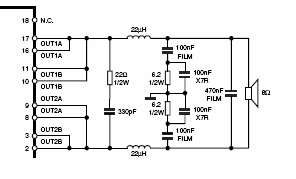
sayang001 said:I'm going to mod the output on my broken board to this shematic:
...
There is a nice article on output filters on class-D amps on this site.
I found it in another thread also discussing output designs.
audio1st said:
I am like you and read lots of info on the internet, it can be conflicting sometimes.
Anyway, I found the link below which if I made any sense of it said that using a low esr cap on the output of the reg was a step in the wrong direction. Panasonic FM quickly removed..
Now it sounds better with the Tantalum to me, but may have been even better with the original

http://www.acoustica.org.uk/t/3pin_reg_notes3.html
Thanks for the update Audio1st. I've just ordered a a few tantalum caps...

Is my calculation correct?
Thank you, ElFishi, for the nice article. I don't fully understand it but I am getting a better idea of output filters.
If I understand correctly, what's known as "common mode filter with damping resistors" in the article seems to be the design to go for if I am willing to spend a little more on the multiple film capacitors required by it.
Can you guys check if I have understood correctly and have made correct calculations? I tried to come up with the values to be used for the inductors, capacitors and registers for this design by following the article.

I am assuming cut-off frequency of 80KHz as written in the Tripath manual and Speaker Load resistance of 4Ohm (for my speakers)
The optimum value for the filter inductor is L = RL/2pi fc, according to the article so this gives me the L value of 7.968127 uH , or about, 8uH
But since the total inductance is divided between two inductors,
L1 = L2 = ½L = RL/(4 pi fc) = about 4uH
And the capacitors are
C1 = C2 = C3 = C4 = 2/((2pi fc)2 • L) = 1/((2 pi fc)2 • L1) = 0.98946uF or about 1uF
and
R1 = R2 = 1/(√2 • 2pi fc C1) = 1.4067442 = about 1.4 Ohm
Am I understanding it correctly? Have I made the calculations correctly?
There is a nice article on output filters on class-D amps on this site.
Thank you, ElFishi, for the nice article. I don't fully understand it but I am getting a better idea of output filters.
If I understand correctly, what's known as "common mode filter with damping resistors" in the article seems to be the design to go for if I am willing to spend a little more on the multiple film capacitors required by it.
Can you guys check if I have understood correctly and have made correct calculations? I tried to come up with the values to be used for the inductors, capacitors and registers for this design by following the article.
I am assuming cut-off frequency of 80KHz as written in the Tripath manual and Speaker Load resistance of 4Ohm (for my speakers)
The optimum value for the filter inductor is L = RL/2pi fc, according to the article so this gives me the L value of 7.968127 uH , or about, 8uH
But since the total inductance is divided between two inductors,
L1 = L2 = ½L = RL/(4 pi fc) = about 4uH
And the capacitors are
C1 = C2 = C3 = C4 = 2/((2pi fc)2 • L) = 1/((2 pi fc)2 • L1) = 0.98946uF or about 1uF
and
R1 = R2 = 1/(√2 • 2pi fc C1) = 1.4067442 = about 1.4 Ohm
Am I understanding it correctly? Have I made the calculations correctly?
C1 = C2 = C3 = C4 = 2/((2pi fc)2 • L) = 1/((2 pi fc)2 • L1) = 0.98946uF or about 1uF
Sorry... it was meant to be power of 2, not multiply by 2
C1 = C2 = C3 = C4 = 2/((2pi fc)^2 • L) = 1/((2 pi fc)^2 • L1) = 0.98946uF or about 1uF
ElFishi said:
There is a nice article on output filters on class-D amps on this site.
I found it in another thread also discussing output designs.
Article is written by people from ST, my drawing comes from the datasheet of the STA505 from ST...
Hi,
Looks like this thread is pretty quiet since the DIYAudio when into maintenance mode over the last few days.
I have a few things to report. This is in reference to the 2*100Watt from Sure electronics module I bought recently.
1. After the item arrived I burned in the unit(unmodified) for a few days by playing music and I hade been listening to music over this period. I powered it from a Laptop smps, 19.6VDC.
The sound quality was not very impressive, even when compared to the chipamp. Very opaque and dull.
2. Then I changed the power supply to battery(4 units,each 12V DC connected in series and parallel) to give me 24V DC. The sound now was much better cleaner and less opaque.
Overall some improvement. I liked to report that I had been using the unit with the battery units for over 10 hours and the voltage dropped marginally from 25.2V to now 24V Dc after more than 10 hours usage. I had a charging circuit in preparation to charge it up once it dropped below 23.5V.
3. Now all the components to modify the circuit had arrived. I changed the following:
a. input caps to Sonic caps, 2.2uF in parallel with 0.1uF, removed the existing caps(1.0uF and 0.1uF) as specified by Audio1st and also the input 22K resistor. More importantly the input suppressor? located underneath the board, this suppressor must be removed for the unit to work properly.
b. removed all the 6 power caps(220uF each) there were very light indeed, replaced them with panasonic 2*1500uF(one in each rail) used by Audiosector.
c. Used a 50k pot from gigaworks similar to the one ordered by Col. It was a SMD resistors connected and make it into a audio log pot.
The bottom line is it sounded like a different amp., very clean and open airy, throws a large sound stage. I own many amps before, inclu. chipamp(LM3886 and 3875) and tubes and solid state. This one sounded very good indeed comparable if not better. If I add up the costs, it will not be over US$100 parts incl. Sure unit, battery, caps and pot. A bargain.
I am listening to it now and enjoying it. Cheers have a good day.
Iv'e something to report as well. I was using a 19v laptop SMPS and thought I was getting good results. I recently found a 24v "universal" laptop SMPS on Ebay and decided I would give it a try. It's made a big difference, more dynamic, plays louder, even the noise floor is lower. I think the 24v "universal" i got is a very cheap SMPS but just having the extra 5 volts makes a big difference.
col.
col.
Thanks to Audio1st, Cheric and dr. Vega and everyone else on this thread!
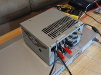
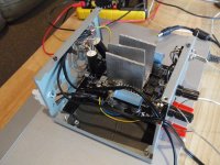
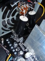
I made the mods and used an old PC power supply as case. I'm VERY happy.
Question: The only issue is that it plays very loud (if I turn the pot it plays even louder! ). I'm using a Radioshack 100k stereo pot. The 4 switches are set to low. Would I need to add more resistance?
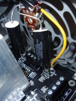
Update: I added photos to show more of the detail of the input side. It's very loud, but very nice detail with my cheapy sony dvd player. I'm currently using a discman to have better attenuation.
I made the mods and used an old PC power supply as case. I'm VERY happy.
Question: The only issue is that it plays very loud (if I turn the pot it plays even louder!
). I'm using a Radioshack 100k stereo pot. The 4 switches are set to low. Would I need to add more resistance?Update: I added photos to show more of the detail of the input side. It's very loud, but very nice detail with my cheapy sony dvd player. I'm currently using a discman to have better attenuation.
Attachments
Last edited:
Help!
My second TP2050 board is having an issue...
I did the "Audio 1st mod", using the input caps off-board and it is working fine but when I add the extra power caps to the board, via the two screw-in terminals, I would loose one channel. Only one speaker would put out the sound. The other one does not have power. My caps are 6800uf / 50V Elna (even when using just one cap). BTW, at this time, I am using a 13.8Volts / 4Amp P/S as I am waiting for the 24v / 6Amp to be delivered from Ebay.
Would the low voltage have anything to do with it?
Again, if I removed the power caps, unplugged the power for a second, the unit would work fine again. Just no extra power caps.
Any ideas what caused this?
Thanks in advance.
Last edited:
- Status
- This old topic is closed. If you want to reopen this topic, contact a moderator using the "Report Post" button.
- Home
- Amplifiers
- Class D
- Sure Electronics New Tripath Board tc2000+tp2050