The AEM6000 is an extremely well regarded amplifier making use of Hitachi
lateral MOSFETs. It was designed by David Tilbrook as a successor to the
ETI477, and published in Australian Electronics Monthly in the nineteen
eighties.
With changes in availability of components, the AEM6000 is now extremely
difficult to build. The amplifier was designed prior to the widespread use of
modelling tools, so is not optimised. Additionally it makes use of a large
single-sided PCB, with through-hole components throughout, like most kitset
amplifiers of the period.
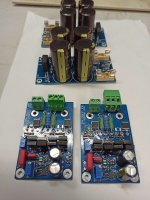
This marks my fourth iteration of this amplifier. My first was reasonably faithful
to the original, differing mainly by substituting 2SK1058 and 2SJ162 flatpack
lateral power MOSFETs for the TO-3 devices in the original, plus substituting
an SST-404 dual JFET for the original input JFET. Iteration two was simply a
50W version of iteration one. This and the iteration three design (100W) alters
the topology slightly, dispensing with the differential-symmetrical VAS stage in
favour of a simpler non-differential stage. VAS and second stage transistors
are higher-performance 2SC3503 and 2SA1381, and the compensation
networks and biasing is optimised for increased amplifier speed whilst
reducing quiescent consumption
Power supply 4x4700uF. Bias 65mA,offset 5mV.
Specifications
Power handling: 50W RMS into 8Ω load.
Frequency response: +/- 0.1dB from 20Hz to 20KHz.
Gain 16 (stable with gain as low as 6).
Distortion + Noise: <0.0005% (1KHz, 0.1W to 50W into 8Ω).
<0.003% (10KHz, 0.1W to 50W into 8Ω).
Noise (input referred): 8nV/√Hz (measured at 10KHz, input shorted).
Slew rate: 10V/μs
Input impedance: 100KΩ (set by resistor).
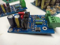
Size: 75mm x 50mm PCB.
Power supply requirement: 2 x 40-60V DC. Lower voltages possible.
Idle power: 5.6W with +/-40V supply.
Price 90€
lateral MOSFETs. It was designed by David Tilbrook as a successor to the
ETI477, and published in Australian Electronics Monthly in the nineteen
eighties.
With changes in availability of components, the AEM6000 is now extremely
difficult to build. The amplifier was designed prior to the widespread use of
modelling tools, so is not optimised. Additionally it makes use of a large
single-sided PCB, with through-hole components throughout, like most kitset
amplifiers of the period.
This marks my fourth iteration of this amplifier. My first was reasonably faithful
to the original, differing mainly by substituting 2SK1058 and 2SJ162 flatpack
lateral power MOSFETs for the TO-3 devices in the original, plus substituting
an SST-404 dual JFET for the original input JFET. Iteration two was simply a
50W version of iteration one. This and the iteration three design (100W) alters
the topology slightly, dispensing with the differential-symmetrical VAS stage in
favour of a simpler non-differential stage. VAS and second stage transistors
are higher-performance 2SC3503 and 2SA1381, and the compensation
networks and biasing is optimised for increased amplifier speed whilst
reducing quiescent consumption
Power supply 4x4700uF. Bias 65mA,offset 5mV.
Specifications
Power handling: 50W RMS into 8Ω load.
Frequency response: +/- 0.1dB from 20Hz to 20KHz.
Gain 16 (stable with gain as low as 6).
Distortion + Noise: <0.0005% (1KHz, 0.1W to 50W into 8Ω).
<0.003% (10KHz, 0.1W to 50W into 8Ω).
Noise (input referred): 8nV/√Hz (measured at 10KHz, input shorted).
Slew rate: 10V/μs
Input impedance: 100KΩ (set by resistor).
Size: 75mm x 50mm PCB.
Power supply requirement: 2 x 40-60V DC. Lower voltages possible.
Idle power: 5.6W with +/-40V supply.
Price 90€
Attachments
Last edited:
