I have designed a regulator for high current directly heated tubes, tubes like the 211/845 on the low end of the current scale and 833 (10V 10A) on the high end of the current scale.
I want to start my own company, and this is perhaps one of the last times you can get this kind of product from me at hobby prices.
The module functions as a automatically adjusted current source, and has voltage control for low frequency, and behaves as a current source for high frequency.
I currently have eight boards left that aren't allready spoken for out of a total PCB order of 20 boards.
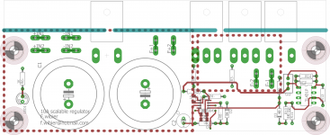
The boards measure 50x160mm and are 1.6mm thick green FR4 epoxy with ENIG-ROHS gold plated pads and 2Oz copper. There is a strip approximately 15mm wide along the length of the board that can be used to mark out the mounting holes of the TO-247 Devices.
Everything needed for the supply except for the bridge rectifier and optional secondary fuse is included on the board. It takes the output of the bridge rectifier and or LT4320 based ideal bridge and stores the charge in the two on board 22000uF capacitors.
The modules are adjustable in its maximum current output by means of swapping out the TO-247 current sense resistor for a different value.
Design specifications where as follows:
Voltage output : Adjustable between 7.5 and 21VDC
Current output : Continuous 3-10A peak for starting cold heaters 5-15A.
Dropout voltage : <=1.5V
Regulation : 0.1% per volt.
Residual hum+ noise : <=2.5mVRMS at rated current output between 10-100Khz.
Suggested retail for one tested board is 125Eur , you get one tested board, and another one without the ROHS-ENIG finish and 1Oz copper instead of 2Oz copper for marking out the holes. Tested boards are de mounted from a test heat-sink, and might have some thermal grease on the semiconductors and FETS. They are complete with everything, mounting hardware and all, the only thing you need to do is mark out 8 holes, four M3 and four M4 on your heatsink of choice.
I am currently taking solid reservations for these modules at a reservation cost of 25Eur to be deducted from the price of 125 Eur for one tested completed module. The price will increase to 175 Eur once all the specifications and correct functioning of the modules has been verified. If it doesn't work or meet the specifications. I will refund you the downpayment on the modules.
From you i need to know what kind of current and voltage range you want as this determines the working voltage of the capacitors, and the value of the shunt resistor.
I have been looking at a company to manufacture 6-8mm thick 80x160MM copper heat spreaders so i can supply. complete modules that bolt on to an existing heat sink with ease, but the prices quoted so far make it a rather expensive proposition.
I will answer any questions you may have through a PM.
Cheers,
V4lve
I want to start my own company, and this is perhaps one of the last times you can get this kind of product from me at hobby prices.
The module functions as a automatically adjusted current source, and has voltage control for low frequency, and behaves as a current source for high frequency.
I currently have eight boards left that aren't allready spoken for out of a total PCB order of 20 boards.
The boards measure 50x160mm and are 1.6mm thick green FR4 epoxy with ENIG-ROHS gold plated pads and 2Oz copper. There is a strip approximately 15mm wide along the length of the board that can be used to mark out the mounting holes of the TO-247 Devices.
Everything needed for the supply except for the bridge rectifier and optional secondary fuse is included on the board. It takes the output of the bridge rectifier and or LT4320 based ideal bridge and stores the charge in the two on board 22000uF capacitors.
The modules are adjustable in its maximum current output by means of swapping out the TO-247 current sense resistor for a different value.
Design specifications where as follows:
Voltage output : Adjustable between 7.5 and 21VDC
Current output : Continuous 3-10A peak for starting cold heaters 5-15A.
Dropout voltage : <=1.5V
Regulation : 0.1% per volt.
Residual hum+ noise : <=2.5mVRMS at rated current output between 10-100Khz.
Suggested retail for one tested board is 125Eur , you get one tested board, and another one without the ROHS-ENIG finish and 1Oz copper instead of 2Oz copper for marking out the holes. Tested boards are de mounted from a test heat-sink, and might have some thermal grease on the semiconductors and FETS. They are complete with everything, mounting hardware and all, the only thing you need to do is mark out 8 holes, four M3 and four M4 on your heatsink of choice.
I am currently taking solid reservations for these modules at a reservation cost of 25Eur to be deducted from the price of 125 Eur for one tested completed module. The price will increase to 175 Eur once all the specifications and correct functioning of the modules has been verified. If it doesn't work or meet the specifications. I will refund you the downpayment on the modules.
From you i need to know what kind of current and voltage range you want as this determines the working voltage of the capacitors, and the value of the shunt resistor.
I have been looking at a company to manufacture 6-8mm thick 80x160MM copper heat spreaders so i can supply. complete modules that bolt on to an existing heat sink with ease, but the prices quoted so far make it a rather expensive proposition.
I will answer any questions you may have through a PM.
Cheers,
V4lve
Attachments
You'll be able to get the price down on that heat spreader if you go with aluminum. You really don't need copper... Also, see if you can use a standard extrusion (aluminum flat bar). That'll cut cost as well. But, yeah... Expect to have to get ~100 made to get them at a decent price.
If you're looking to mass produce circuits (say QTY 100-250 per batch), you'll want to use SMD components. Just saying. Assembly by hand does not scale and it's expensive to have others do it for you.
If you'd like some input on your business setup or ideas, just toss me an email (add @neurochrome.com to my user ID here). I'm more than willing to share my experience via email or in a Skype call. Free of charge. Just one forum member helping another.
I love running my own business. I earn maybe 20-25% of what I used to earn at National/TI, but I'm having ten times the fun and one tenth the stress.
Tom
I have been looking at Aluminium strip so far, however the people that have ordered ten so far have indicated they don't need the spreader capability.
Getting a piece of aluminium to serve as a heat spreader is the easy part of the equation, if i drill these myself tolerances mean that no single piece is exactly alike to the others. And getting them machined is out of the question, all through now that i think of it, i do know a guy.
I know i want to have the design SMD once i do larger batches. But the marked for these kind of regulators is so low i dont mind doing the SMD for the modules, its about 5 minutes of work for each.
My problem with an earlier design was that JLCPCB didnt stock the MELF 0207 resistors i preffered. so i ended up soldering 20+ units by hand.
I will send you an email sometime this week, im interested to hear from you.
Once i get the specs verified i will post some measurements here, this module is supposed to have soft ramp up on the current regulation. First tube i'm going to try is the 813.
Cheers,
V4lve.
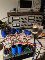
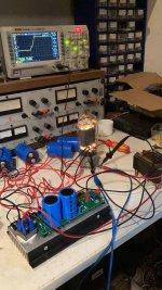
Some pictures, it seems to work ok
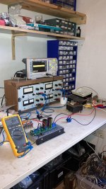
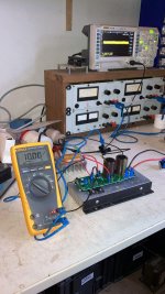
Here are some pics, i got the boards in yesterday, and found the time to build one into a unit on a test heatsink.
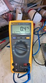
This one is trimmed to 10.0V on a 3.0R load for a load current of about 3A, or the equivalent of a 211
with a 12VAC transformer input, i'm measuring the noise unshielded with my fluke multimeter. And its lower than 0.5mV RMS.
Regulation seems to be up to spec as well, i am waiting for a friend to drop of some 813's so i can test the heater startup behaviour.
Here are some pics, i got the boards in yesterday, and found the time to build one into a unit on a test heatsink.
This one is trimmed to 10.0V on a 3.0R load for a load current of about 3A, or the equivalent of a 211
with a 12VAC transformer input, i'm measuring the noise unshielded with my fluke multimeter. And its lower than 0.5mV RMS.
Regulation seems to be up to spec as well, i am waiting for a friend to drop of some 813's so i can test the heater startup behaviour.
Attachments
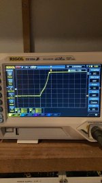
some additional pictures of the start up behaiviour of a 813
See the attached picture of the scope plot, these modules start up a tube in a controlled manner.
See the attached picture of the scope plot, these modules start up a tube in a controlled manner.
Attachments
- Status
- This old topic is closed. If you want to reopen this topic, contact a moderator using the "Report Post" button.
- Home
- Vendor's Bazaar
- DHT regulator for 3-10A continuous 10-21V out.