I would appreciate any advice I can receive. I recently picked up this amp and was told by the previous owner that it was blowing the 3 amp fuse. I checked the output tubes and found one bad one. I plug the unit into a variac and had a cd player plugged into the input and 2 small speakers hooked up. I slowly brought the power up and when I reached about 80 volts could hear music coming out of the speakers. All of a sudden R39 blew up. I replaced the resistors in the bias circuit. I can't check the bias because I'm afraid to power up all the way. I deceided to check the voltage at TP 1 and 3. It should be around 107volts at full power but I'm getting 180v with the amp only half way powered. Any ideas where to look to solve the increase in voltage?
Attachments
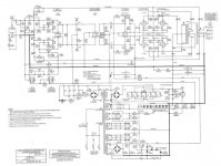
Sorry, but ur posted schematic is too small to see the parts ID.
In general, pull the output tubes, the input tubes, and bring the thing up on the variac, around 70-80vac line voltage the fils on the rectifiers will start to conduct - BUT WAIT! - it's a solid state bridge, so just bring up the voltage, and watch to see that all the PS voltages are ok. Including the bias voltage
You should be able to see that all the voltages are about right... keep the input voltage around 100 - 105vac, and the PS voltages ought to be about correct as compared to full input voltage and the tubes in place.
Set the bias voltages with no tubes in the output stage to the tube book's nominally correct voltage.
Next test the amp's input section... look for leaky signal caps... DC appearing on the grid side of a coupling cap.... if that tests OK, Signal in, and looks good on a scope... then take out one side's input tubes... power down, and plug in a pair of output tubes that would be a P-P pair out of the 4 and see if the amp works.
Repeat for the second channel.
Add in the second pair of tubes
Repeat back on the other side.
Somewhere in there you should find a big fault.
You checked the nominal bias voltages back in the first part.
Ok?
_-_-bear
Edit:
Well happens I have the schematic on my HD...
The B+ is regulated or ballasted by V19... or so it seems.
Check the ZD string that runs to the grid of V19.
Check V19.
Check that the B+ is 410vdc.
V9 has to be Ok too. So if the problem is only on one channel, pull that channel's V9 and try the other one in the hole too.
The ZD string puts the fils of the driver tube low so that the cathode/fil voltage max is not exceeded, since the cathode of the driver applies the bias to the tubes and is DC coupled to the grids.
Fwiw, I'd have chosen a different means of DC coupling the cathode of the driver tube to the output tube grids. But this obviously does work.
Interesting that ARC seems to have abandoned their X-coupled stages in this amp.
R39 is a screen resistor, if it blew up either the tube is bad or the screen is drawing massively too much current.
- Status
- This old topic is closed. If you want to reopen this topic, contact a moderator using the "Report Post" button.