Folks:
I've been working on a 2 chassis Aikido preamp for nearly a year -- my progress has been in fits and starts, mostly due to work and family demands. I've been worrying over one aspect of the build for a while, and would appreciate some advice:
The power supply chassis will provide the two B+ lines and the 6.3VAC power needed to drive the four tubes in the preamp chassis. A single umbilical cord will pass the various voltages from the power supply chassis to the preamp chassis (both AC and DC). Each discrete power line in the umbilical is shielded, using 0.25" metal sheathing (in fact, there are four separately-sheathed twisted pairs in the umbilical). I understand that it may be helpful to have an simple RC network at the preamp chassis to help clean up the incoming B+ lines.
Can anyone suggest values for the resistor and capacitor used to tame the incoming B+ lines; alternatively, can anyone help me to understand how those values should be determined?
Thanks for your counsel!
Regards,
Scott
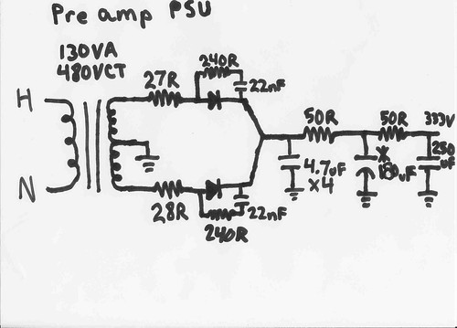
Bleeder resistor omitted from diagram. Parts values were in part determined by stock on hand. This is also a mono psu, for stereo Id recommend splitting the last RC section into an RC section for each channel. High gain amps might want more resistance and/or sections.
Id do all but the last sections on the psu chassis, why put ac dirt on the other chassis. Take care to avoid ground loops.
Id do all but the last sections on the psu chassis, why put ac dirt on the other chassis. Take care to avoid ground loops.
Assuming that B+ is smooth enough with the PS as drawn, then I would think a good quality 0.1 uF 450v cap from B+ to ground, in the preamp itself, would be adequate. What you want is a good signal path to ground, without having to go through the umbilical to the PS to find such a path.
All:
Thanks for the counsel!
I should have mentioned this in my post, but the Aikido preamp is being built using Bas Horneman's beautiful little PCBs. As a result, I suspect that the bulk of the B+ smoothing that Tweeker described in his diagram is already accounted for in Bas's power supply PCB. However, I certainly can add a resistor and small value/high voltage capacitor to each B+ line at the preamp chassis, as recommended by both Tweeker and ray_moth.
ray-moth's suggestion that the preamp chassis ground not run through the umbilical is understood, but may be somewhat impractical; unless there is a safety issue, I'll try using the umbilical ground first, and will resort to a separate ground only if I hear a problem (it's nice to address aesthetic concerns where possible).
And Mikael, you are correct -- if I'm to ever learn anything lasting from this experience, I ought to try my hand at modelling. Baby steps for this newbie, but Duncan's PSU Designer will have to become part of my learning curve.
Thanks again!
Regards,
Scott
- Status
- This old topic is closed. If you want to reopen this topic, contact a moderator using the "Report Post" button.
- Home
- Amplifiers
- Tubes / Valves
- Basic RC Value Question