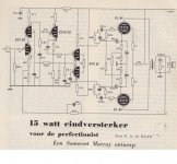
Besides the usual cathode degeneration and the overall loop, the only "extra" I see is from the output tube plates to the driver cathodes. That's a good idea in pentode output stages.
The designer didn't take advantage of the multiply tapped output transformer secondary to provide cathode feedback for the output tubes.
The designer didn't take advantage of the multiply tapped output transformer secondary to provide cathode feedback for the output tubes.
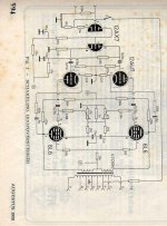
There is also feedback from the secondary of the output transformer, take another look... ") The way it is drawn makes it less obvious, but it is derived from one of the intermediate output taps. (Seems like this output transformer might be able to do balanced 600 ohm and some other odd things, I think that tap might be the 8 ohm tap.)
The way it is drawn makes it less obvious, but it is derived from one of the intermediate output taps. (Seems like this output transformer might be able to do balanced 600 ohm and some other odd things, I think that tap might be the 8 ohm tap.)
Take a look at the Citation II schematic, there are several loops in that design as well. (Early 1960's) The Citation II actually is a very good sounding amplifier, and that from a guy who is avowedly a single ended devotee..
The way it is drawn makes it less obvious, but it is derived from one of the intermediate output taps. (Seems like this output transformer might be able to do balanced 600 ohm and some other odd things, I think that tap might be the 8 ohm tap.)Take a look at the Citation II schematic, there are several loops in that design as well. (Early 1960's) The Citation II actually is a very good sounding amplifier, and that from a guy who is avowedly a single ended devotee..
There is also feedback from the secondary of the output transformer, take another look...
That's what I meant by "overall loop." Sorry, didn't mean to be cryptic.
Re: to keep you busy
An interresting way to balance DC in the Push Pull.
Yves.
Jaap said:here another unusual design from 1966 in the same magazine. Nice to try those feedback options.
An interresting way to balance DC in the Push Pull.
Yves.
- Status
- This old topic is closed. If you want to reopen this topic, contact a moderator using the "Report Post" button.