O.K just recently I happen to get cheaply 2 pairs of interstage transformers one ampex 1:1 type 4580200 and a pair of huge output transformers specified 9900 center taped to 500 CT, 60ma balanced DC 20-20KHz +/-1dB. I was thinking of a simple P-P line amplifier (L.Olson's amity style)with 6H6p or similar. Is this a viable project or should I abandon it ?
Any proposals would be greately appreciated.
Any proposals would be greately appreciated.
Hi Panos,
It's viable and I have built just such a 6N6P PP pre-amplifier. It's was really nice.
I tried the CCS on the cathodes and a straight resistor. I preferred the sound of the resistor, i.e run in push pull rather than differential. Some people prefer differential...
The bypass cap between the OPT CT and the common cathodes should be bigger by an order of magnitude. It's bypassing the parallel Rps of the tubes so about 1200R. For a 4Hz F3 about 33uF is indicated. I guess Rp is probably higher at your operating point but still...
I generally run the 6N6P a bit hotter than you suggestion but I suggest you try it at different points and see what works best.
Have fun, it's a nice idea
James
Dissapointed
Thank you James, I tried with and without cap and also tried 10u and 15u mkp. To tell the truth I did tried the shown arrangement (with the output driving a 4k7 resistor load and I was dissapointed.
First of all the circuit seems to have a gain lower than 3X, which is not at all a problem but seems odd.
On the other hand, square wave test seems to fail alot past 1KHZ which is sure bad.
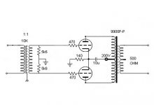
I really believe that something is wrong as far as the input transformer termination is concerned. The input transformer is a 1:1 that supposed to be 20k bridging transformer(1k5:1k5 dc resistance) used at the input of all huge ampex studio recorders.
Any ideas?
Thank you James, I tried with and without cap and also tried 10u and 15u mkp. To tell the truth I did tried the shown arrangement (with the output driving a 4k7 resistor load and I was dissapointed.
First of all the circuit seems to have a gain lower than 3X, which is not at all a problem but seems odd.
On the other hand, square wave test seems to fail alot past 1KHZ which is sure bad.
I really believe that something is wrong as far as the input transformer termination is concerned. The input transformer is a 1:1 that supposed to be 20k bridging transformer(1k5:1k5 dc resistance) used at the input of all huge ampex studio recorders.
Any ideas?
Hi Panos, James
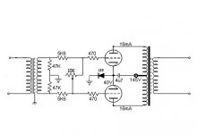
something doesn't seem correct with the diagram indicated 40v on cathode accross an LED to my mind that led should have left the planet when the filaments warmed up (also given 16ma + 16ma indicated in the Anodes 32ma total mmm) have I missed something?
would have thought a constant current circuit would have been beter, there is a fine line between PP and diffmost to do with CMRR.
PS most of the old broadcast gear had very nice i/p transformers in them alas most are ending up as land fill ;o((
Robert
Right!
Hello Robert,
Yep you are correct, the fact is that i just copied the basic circuit from the net and forgot to change the values, as well as led symbol. In place of the led I got a 140ohm resistor and the B+ is at 200V.
I played a bit with this circuit and I found great improvement to the square waves using 11K as load for the ampex transformer. Overall the squares are not perfect after 2KHz but still acceptable.
Another thing that I have to tame, is how to adjust volume without spoiling the HF responce and to find out why the amplification factor is only around 2X.
Any idea?
About the transformers now, you are absolutely right! there are too many super ones dambed somewhere roting. I found mine in a huge junk pile 5meters high in a surplus junk yard where these use to wait their turn to be melted for copper!!! I also have some similar ones but not in pairs.
Attachments
")

Hi Panos,
Having a hunt for some data on the input trannies, I found them described as 600R:600R input trannies or as 15K:15K input bridging trannies! Not much difference then!
One thing that can cause significant hf roll off is if you have one of the windings connected the wrong way around. Have you tried it connecting it both ways around?
The other thing I would try is to put the pot. infront of the input transformer - yes I know it is 'wrong' but I find it works better for me there.
ciao
James
Hi All,
I got more then i expected there is another thread on this very subject.
as for the gain mmm not sure I guess the 470r cathode resistor being un-bypassed might shift the plate r but hey thats a guess.
for configuration A (i like that the best) and from the other thread also makes good sense add a 1M r to ground from both grigs. because if the pot goes oc or just noisy you will have a floating grid mmm not so nice on the tube.
most of the i/p transformers were usually 10k primary that way you could just switch a 600r resistor across the i/p to terminate the audio source, the broadcast world use to use 600r source z now days most everything is voltage feed! i.e. low z source and hi z i/p.
have you looked at the response from the transformer only and maybe look at terminating the secondary into it's expected Z and see if you still have response problems
also if there is an es shield ground it to reduce capacitive coupling between pri and sec.
Robert
Thanks everybody for the great help, I finally gor around the problems I had! I loaded the secondary of the input transformer with 10K measuring the point where I had the best square wave respnce and everything now is alot better. I will test both options for volume control with sole criterion the square wave responce and report on my findings.
- Status
- This old topic is closed. If you want to reopen this topic, contact a moderator using the "Report Post" button.
- Home
- Amplifiers
- Tubes / Valves
- Push Pull Preamplifier anybody?