Hi
I'm looking for complete datasheet and diagram for 12FV7.......
I can only find some brief data on TDSL......
So if anyone has the full datasheet of 12FV7, please kindly help.
thanks!
Coffin
I'm looking for complete datasheet and diagram for 12FV7.......
I can only find some brief data on TDSL......
So if anyone has the full datasheet of 12FV7, please kindly help.
thanks!
Coffin
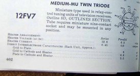
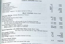
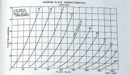
This is what I have from a 1963 RCA tube manual. It is in three seperate pictures to preserve readability and meet file size requirements. I have tried these tubes. They work well as drivers, like a 12BH7, but the ones that I have (RCA's) are too microphonic for input tubes.
Attachments
Hi
Thank you very much!
I also see you use IXYS 10M45 as active load.
Have you compared it with choke-load?
thanks again
Coffin
Thank you very much!
I also see you use IXYS 10M45 as active load.
Have you compared it with choke-load?
thanks again
Coffin
I have not compared it with any good quality chokes that were designed for an audio load. All of the chokes that I have are removed from the power supplies of surplus electronic equipment.
Given that fact I prefer the sound of the CCS IC. Several people who saw the PowerDrive circuit on the web site have e-mailed me explaining how it did wonders for their sound, but I don't have the details of each persons experience.
The drawback to the CCS load is that you need a lot more B+ voltage than an equivalent circuit using a choke. The B+ must be higher than the quiescent plate voltage, plus the peak expected signal swing. This is not usually a problem in low level circuits, but becomes a factor when driving the grid of an 845.
hi
Thanks for your detailed description.
My friend had tested the 10M45 on driver stage on 300B, he said "amazing".....
He also said that the spec curve on PDF is a little bit different from his testing.
On PDF, if R=91R, There will be 30mA.
But he use 66R to get 27mA, and 120R with 17.8mA.
Is that correct? Have you compare that?
Suddenly this thread becomes 10M45 disscussion.....
cheers
Coffin
I use 330 ohms to get 11 to 12 mA with a 5842 tube. I am using 91 ohms to get about 30 mA with a 45 tube. Every chip is slightly different than the next one.
The 10M45 has a strong tendency to oscillate in the VHF region. To fix this I added a "gate stopper" resistor of 1K ohms in series with the G (gate) terminal of the device. The resistor should be located as close to the chip as possible. Oscillations can cause strange current readings, and chips that mysteriously die.
The schematic is on my web site : http://www.tubelab.com/845SE.htm Look at the third one labeled 845SE amp. That is the current schematic that I have been using. That amp has played flawlessly for over a year.
Hi Coffin,
That's been my experience too, the datasheet's recommended resistor values don't quite work. I got around it by fixing a ten-turn pot to the chip to facilitate easy changes while the circuit's in operation. These chips are so cheap it's worth putting together a couple of these variable circuits for development purposes, you can always use measured resisitor values when building the final circuit. I also follows tubelab's 'gate stopper' recommendation with an additional series resistor on the output to buffer the chip from load reactances. Consider the latter voodoo but to my ear it helps.
For what it's worth I recently compared a Hammond 156C (so-so plate choke, self-resonant about 2.1 kHz) against the IXYS as plate load for a triode connected E810F driving an EL84. Mid-band the choke/E810F combo was making less than .03% THD at about 3 Vrms yet the IXYS made a fascinating difference, sounding 'darker' and less romantic. Possibly a touch smoother on sibilance as well. The 156C circuit was ~ 1 dB down at 120 kHz, the IXYS dead flat so it's wasn't a frequency abberation. No idea how it was audible through the output's 2.5% but there you go. Maybe it has something to do with the choke's higher distortion down low. Both sounded great and since the 810 is fed from an 0D3 both were dead quiet, and I mean 'late night ear to a 94 dB efficient speaker's dust cap to hear any hiss' quiet. I'm still not sure which I prefer.
Hi
Thanks you guys to explain it thoroly.
I'll try to replace the 270H plate choke loaded for EC88 on my SE amp with 10M45, to see there's any improvement.

cheers
Coffin
Thanks you guys to explain it thoroly.
I'll try to replace the 270H plate choke loaded for EC88 on my SE amp with 10M45, to see there's any improvement.
cheers
Coffin
Beautiful amp, hope it sounds as good as it looks! I don't recognize the output tubes, what are they?

- Status
- Not open for further replies.
- Home
- Amplifiers
- Tubes / Valves
- help 12FV7 datasheet