That setup can work extremely well! The choke also benefits you by getting rid of more power supply ripple at the same time while getting the DC issue out of the output xfmer. You should also experiment with placing the signal return capacitor from the output transformer directly to the output tube cathode rather than chassis ground.
Hi rcavictim,
Which is ? Secondary winding ? I think I don't get that setup. Can you point me a schematic ?
rcavictim said:You should also experiment with placing the signal return capacitor from the output transformer directly to the output tube cathode rather than chassis ground.
Which is ? Secondary winding ? I think I don't get that setup. Can you point me a schematic ?
For parallel feed, you can replace the choke with a ccs like Gary Pimm's which can greatly simplify PSU design.
Re: cap to cathode, Mr.Pimm also discusses this somewhere on his site.
Re: cap to cathode, Mr.Pimm also discusses this somewhere on his site.
yagoolar said:Which is ? Secondary winding ? I think I don't get that setup. Can you point me a schematic ?
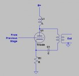
I'm not rcavictim but I think he means something like this
Attachments
audiousername said:
I'm not rcavictim but I think he means something like this
Audiousername,
Yes that is exactly the circuit that I was referring to!
yagoolar said:Hi,
I once found a pdf with such a schematic. It was published on bottlehead web page. The amp is called Lizzy (by Anthony Dockrill). I am curious what you think about the output stage and xformer connection. Has anyone tried it ?
The circuit you showed has the 6L6 output tube wired as a cathode follower in parafeed mode. Since the output tube now has less than unity gain an extra (noise generating) gain stage must be added to what could be a simpler total amplifier circuit. This is very uncommon, at least from my sheltered experience. This would allow the use of a rather low primary Z output xfmer, but he has placed a rather high Z transformer of 3K here. I am a bit baffled by this. I see he places the speaker winding in series with the primary to turn the OPT into a autoxfmer. This further increases the Z of the output transformer albeit by only a small fraction. This is fine since there is no DC and must increase fidelity a bit. IMO the 1 uF output coupling cap is way undersized.
Where do you guys find this stuff?

rcavictim said:
The circuit you showed has the 6L6 output tube wired as a cathode follower in parafeed mode. Since the output tube now has less than unity gain an extra (noise generating) gain stage must be added to what could be a simpler total amplifier circuit. This is very uncommon, at least from my sheltered experience. This would allow the use of a rather low primary Z output xfmer, but he has placed a rather high Z transformer of 3K here. I am a bit baffled by this.
Looking at the schematic, it appears that the designer had 10Y valves around, wanted to use them but also required low output impedance, which the 10Y couldn't provide because of its high-ish rp. So, the 6L6 is used in CF to prodvide low output Z.
So the question is... why wasn't a lower rp valve used to start off with? I guess it's because of the lure of old, rare and EXPENSIVE valves... argh... an ordinary $6 12E1 in triode may very well have performed better.... (and given more power) But I could be wrong, wouldn't be the first time...
Rant mode over...
")
Yagoolar, that is not the typical shunt-feed (parafeed) output stage. Check this out: http://members.aol.com/sbench/outstru.html It's an article by Steve Bench outlining the most common (and some of the less common) output structures for valve amplifiers.
ultrapath and parallel feed
Good morning all,
i do fully agree with rcavictim's remark about the 1 uF value; way to low !
The proposed schematic is a nice combination of ultrapath (Jack Elliano, Electraprint, etc) and parallel feed. This combination is sometimes referred to as "ultra parafeed". It is certainly not new, Western Electric used it already in 1938 in their 92B-amplifier.
Ultra parafeed does have some nice features:
- the coil will take care of DC-component. So you can optimize the OPT with more exotic cores. Or use a smaller winding to decrease the resistance. Either way......the OPT can be better (and there is no air gap as well).
- the extra cap does seem to smooth out a lot of power supply irregularities.
Of course there are trade-offs no surprise:
- the coil is not a standard choke !
- there will be an extra cap between the OPT and the cathode. This must be a quality item ! I do favour a nice oil cap here......but that is a matter of taste.
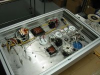
Lynn Olson wrote in VTV (issue 16) a very informative article about these topologies under the name "Ultrapath, parallel feed and Western Electric". This very article made me base my 833 amplifier on the proposed topology "ultra parafeed". And it does work superbly !
Included a picture of the inside of the 833 amplifier. In the left upper corner you'll see the cap. A 4 uF / 4 kV affair....i did not take any changes with the anode voltage of 1400 V....just to be on the safe side.
Reinout
Good morning all,
i do fully agree with rcavictim's remark about the 1 uF value; way to low !
The proposed schematic is a nice combination of ultrapath (Jack Elliano, Electraprint, etc) and parallel feed. This combination is sometimes referred to as "ultra parafeed". It is certainly not new, Western Electric used it already in 1938 in their 92B-amplifier.
Ultra parafeed does have some nice features:
- the coil will take care of DC-component. So you can optimize the OPT with more exotic cores. Or use a smaller winding to decrease the resistance. Either way......the OPT can be better (and there is no air gap as well).
- the extra cap does seem to smooth out a lot of power supply irregularities.
Of course there are trade-offs no surprise:
- the coil is not a standard choke !
- there will be an extra cap between the OPT and the cathode. This must be a quality item ! I do favour a nice oil cap here......but that is a matter of taste.
Lynn Olson wrote in VTV (issue 16) a very informative article about these topologies under the name "Ultrapath, parallel feed and Western Electric". This very article made me base my 833 amplifier on the proposed topology "ultra parafeed". And it does work superbly !
Included a picture of the inside of the 833 amplifier. In the left upper corner you'll see the cap. A 4 uF / 4 kV affair....i did not take any changes with the anode voltage of 1400 V....just to be on the safe side.
Reinout
Attachments
amplifier using ultra parafeed
Good morning again,
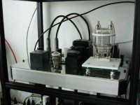
yes i know.....i did already posted pictures of this amp earlier. But that was on a 833-tube thread. And this is about ultra parafeed. And this amp uses a 833-tube in an ultra parafeed schematic.
Again: please use a high quality cap. Value: araound 5 uF gave me good results.
Formula wise:
C = 1 / (6,28 x I x F)
C = capacitor in F
I = ompendance tube in Ohms
F = desired "fall off frequency" (sorry....i do not know the correct phrase)
For the 833:
C = 1/ (6,28 x 5000 ohms x 10 Hz) = 0,000003185 F = 3,2 uF
Much less will impair bass-quality.
Much more is not bringing stability.....on the contrary
Hope this helps ?
Reinout
Good morning again,
yes i know.....i did already posted pictures of this amp earlier. But that was on a 833-tube thread. And this is about ultra parafeed. And this amp uses a 833-tube in an ultra parafeed schematic.
Again: please use a high quality cap. Value: araound 5 uF gave me good results.
Formula wise:
C = 1 / (6,28 x I x F)
C = capacitor in F
I = ompendance tube in Ohms
F = desired "fall off frequency" (sorry....i do not know the correct phrase)
For the 833:
C = 1/ (6,28 x 5000 ohms x 10 Hz) = 0,000003185 F = 3,2 uF
Much less will impair bass-quality.
Much more is not bringing stability.....on the contrary
Hope this helps ?
Reinout
Attachments
Re: ultrapath and parallel feed
Please help me understand this.... does the "Ultra-Parafeed" nomenclature refer to the (conventional) capacitor in series with the OPT primary or that the primary is returned to the cathode of the output valve instead of to ground.
As an aside, I believe but the use of what is now knon as "Ultrapath" was mentioned by John Broskie in the TubeCad Journal in an article something like "lowering the SE amp's output noise", prior to the Jack Elliano article.
This is true... Also of note, I believe that the reasoning of returning the OPT primary to the cathode instead of ground is to stop the PS from being in series with the signal (not sure on this though)
I am not familiar with this article, however if it means that you are using the cathode-follower output stage (as in the schematic proposed by Yagoolar) that must be one very special drive stage!
By the way, splendid looking amp! Only wish I had the patience to make something that looked that good...
ReinoutdV said:The proposed schematic is a nice combination of ultrapath (Jack Elliano, Electraprint, etc) and parallel feed. This combination is sometimes referred to as "ultra parafeed". It is certainly not new, Western Electric used it already in 1938 in their 92B-amplifier.
Please help me understand this.... does the "Ultra-Parafeed" nomenclature refer to the (conventional) capacitor in series with the OPT primary or that the primary is returned to the cathode of the output valve instead of to ground.
As an aside, I believe but the use of what is now knon as "Ultrapath" was mentioned by John Broskie in the TubeCad Journal in an article something like "lowering the SE amp's output noise", prior to the Jack Elliano article.
ReinoutdV said:Ultra parafeed does have some nice features:
- the coil will take care of DC-component. So you can optimize the OPT with more exotic cores. Or use a smaller winding to decrease the resistance. Either way......the OPT can be better (and there is no air gap as well).
- the extra cap does seem to smooth out a lot of power supply irregularities.
Of course there are trade-offs no surprise:
- the coil is not a standard choke !
- there will be an extra cap between the OPT and the cathode. This must be a quality item ! I do favour a nice oil cap here......but that is a matter of taste.
This is true... Also of note, I believe that the reasoning of returning the OPT primary to the cathode instead of ground is to stop the PS from being in series with the signal (not sure on this though)
ReinoutdV said:Lynn Olson wrote in VTV (issue 16) a very informative article about these topologies under the name "Ultrapath, parallel feed and Western Electric". This very article made me base my 833 amplifier on the proposed topology "ultra parafeed". And it does work superbly !
I am not familiar with this article, however if it means that you are using the cathode-follower output stage (as in the schematic proposed by Yagoolar) that must be one very special drive stage!
By the way, splendid looking amp! Only wish I had the patience to make something that looked that good...
rcavictim said:
Where do you guys find this stuff?
Here you are
Pride and Prejudice
I also recommend the article: "Mathematical Derivation of Parafeed Output Stage" from this page.
audiousername,
The ultrapath slogan does indeed refer to returning the AC signal to the cathode of the output valve. The parafeed design places the output valve in the mode of operating as an active shunt to the power supply applied to the output xfmer. Like a shunt regulator stage if you will on a DC power supply. The power supply is not in series wit the output stage in this configuration and is in fact isolated from the output stage by the plate choke which gives this circuit greater PS noise immunity as part of it's charm.
The regular output stage configuration uses the output valve as a series pass element to change the power applied to the output xfmer. The PS is in series with the output stage and any PSU noise/ripple is impressed upon the output signal.
In the ultrapath config the fact that the cathode resistor is not there to do anything good for the audio component, it is only there to provide operating bias for the output valve, is recongnized for what it is and eliminated from the audio circuit. If you wire the return of output xfmer to ground, including the resistance of the cathode R you effectively place an extra R in series with the output xfmer primary that only reduces the % of available audio power that can be taken out of the amplifier. You also introduce a small amount of negative feedback in the output signal which is the changing voltage across Rk.
As stated the two concepts of Ultrapath and Parafeed are nothing new, just perhaps the slogans used to describe them. I employ both these techniques in a parallelled SET amp I designed which uses eight triodes (four 6080's) in parallel in the output stage. BTW, I use 4 uf off the cathode of each individual triode stage for the output coupling caps all going to the bottom of the output transformer primary. High quality metal can, polypropelene and oil motor run caps have been purchased but not yet tried to replace the 3.5 uF mylar dry caps employed in the prototype breadboard which sounds marvelous!
rcavictim,
Would love to see a schematic of your amp. I've recently switched my line stage to this configuration, using a 12B4A into a toroid opt(ala Manfred Huber). I'm using a cheap ccs instead of the plate choke.
I've been leaning toward a ppp parafeed 2A3(pppp2A3?) but am open to other topologies.
Would love to see a schematic of your amp. I've recently switched my line stage to this configuration, using a 12B4A into a toroid opt(ala Manfred Huber). I'm using a cheap ccs instead of the plate choke.
I've been leaning toward a ppp parafeed 2A3(pppp2A3?) but am open to other topologies.
rcavictim said:The parafeed design places the output valve in the mode of operating as an active shunt to the power supply applied to the output xfmer. Like a shunt regulator stage if you will on a DC power supply. The power supply is not in series wit the output stage in this configuration and is in fact isolated from the output stage by the plate choke which gives this circuit greater PS noise immunity as part of it's charm.
The regular output stage configuration uses the output valve as a series pass element to change the power applied to the output xfmer. The PS is in series with the output stage and any PSU noise/ripple is impressed upon the output signal.
Thanks for that. I'd never thought about it that way..
schematic amp
Hi Audiousername,
i wished i could explain the ultra-parafeed like Rcavictim....
Just to hint at the capacitor:
- in a ultrapath-topology the cap-value will be in the 10+ region. It's often used in preamps and don't be surprised to see values between 10~100 uF.
- in the parallel feed and ultra-parafeed you'll see values around the 5 uF. The cap has a somewhat different function here in combination with the coil (as Rcavictim pointed out).
You asked about the driver. You're right about the special quality. But i'm not using a cathode-follower.
The 833 has a huge grid and really likes to see "power" in order to function. So i choose a 300B (can sound really nice) with a stepdown interstage. That also gives me the wanted low impendance....power !
Added is a simple drawing of the shematic:
- XLR in;
- input transformer;
- 6SN7 push-pull;
- interstage;
- 300B "classical SE";
- interstage stepdown;
- 833;
- opt.
Besides nice sounding this amp will also provide the heating during the cold winter days......
Reinout
Attachments
"Should I load the secondary winding of my existing output transformer of my 45 SE amp with a dummy 8 ohms resistor if i were to wire up another parafeed optx in the amp? Is it harmful to just leave the secondary open? "
Yes - voltages in the secondary of an unloaded transformer can spike very high - infact to damaging levels, which could destroy your transformers. However loading your transformer with a 8R resistor will halve your availble power output. Think about a 22R load.
Shoog
Yes - voltages in the secondary of an unloaded transformer can spike very high - infact to damaging levels, which could destroy your transformers. However loading your transformer with a 8R resistor will halve your availble power output. Think about a 22R load.
Shoog
- Status
- This old topic is closed. If you want to reopen this topic, contact a moderator using the "Report Post" button.
- Home
- Amplifiers
- Tubes / Valves
- Parallel feed (choke load) in output stage