I was searching in forums at DiyAudio to take ideas and schems to build my new amp .
So ,with Geek’s and coqsncoqs’ very useful help I tried to design my own schem.
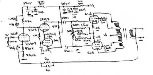
The driver stage , 6SN7 direct coupled to 6FQ7 LTP , is taken by coqsncoqs (a driver stage that he is working with arnoldc for an amp with EL34).
It has around 39.5 db gain . So with 0.5 Vrms input I’ll have 47 V at each output of the phase splitter , right???
Here I have a newbie question. The above means : 47*2=94 V rms from grid to grid ????
According to , Svetlana’s data the SV6L6 PP output stage needs peak 70 V grid to grid voltage or 49.5 V rms . So with an input about 0,25Vrms and without FB I can drive the output stage at full power and have 30W .
Please be patient and if I’m wrong please correct me .
The output stage is designed by me trying to obtain a 6L6 PP UL AB1 at 450V ( Geek’s suggestion) to have Po about 30W.
I’m saying “to obtain” cause ,as a newbie , I don’t know if it’s correct ( Geek haven’t seen it, yet ).
Maybe I’ll do fullish things so don’t freak out!
I have attached the schem , hoping the gurus out there will help me!
So ,with Geek’s and coqsncoqs’ very useful help I tried to design my own schem.
The driver stage , 6SN7 direct coupled to 6FQ7 LTP , is taken by coqsncoqs (a driver stage that he is working with arnoldc for an amp with EL34).
It has around 39.5 db gain . So with 0.5 Vrms input I’ll have 47 V at each output of the phase splitter , right???
Here I have a newbie question. The above means : 47*2=94 V rms from grid to grid ????
According to , Svetlana’s data the SV6L6 PP output stage needs peak 70 V grid to grid voltage or 49.5 V rms . So with an input about 0,25Vrms and without FB I can drive the output stage at full power and have 30W .
Please be patient and if I’m wrong please correct me .
The output stage is designed by me trying to obtain a 6L6 PP UL AB1 at 450V ( Geek’s suggestion) to have Po about 30W.
I’m saying “to obtain” cause ,as a newbie , I don’t know if it’s correct ( Geek haven’t seen it, yet ).
Maybe I’ll do fullish things so don’t freak out!
I have attached the schem , hoping the gurus out there will help me!
Resident,
Can't help you with your amp but in case you want the picture posted, click on 'Browse' in the 'Attach file:' section underneath the reply box.
/Hugo 🙂
Can't help you with your amp but in case you want the picture posted, click on 'Browse' in the 'Attach file:' section underneath the reply box.
/Hugo 🙂
Hi,
No idea what they're up to but using the octal version to drive the same tube but in its noval version doesn't make sense to me.
The 6CG7 and 6SN7 are electrically one and the same, only sockets are of a different type.
As for the rest of your QQs I'd need to see the circuit first to be able to answer.
Cheers, 😉
The driver stage , 6SN7 direct coupled to 6FQ7 LTP , is taken by coqsncoqs (a driver stage that he is working with arnoldc for an amp with EL34).
No idea what they're up to but using the octal version to drive the same tube but in its noval version doesn't make sense to me.
The 6CG7 and 6SN7 are electrically one and the same, only sockets are of a different type.
As for the rest of your QQs I'd need to see the circuit first to be able to answer.
Cheers, 😉

Hope the schem is clearly enough.I don't know how to make good attachments,yet!! 🙁
@fdgrove
I didn't know this.So,I can use 6SN7 with no problem,right?
I find it like it is in the attachment file.
@fdgrove
The 6CG7 and 6SN7 are electrically one and the same, only sockets are of a different type.
I didn't know this.So,I can use 6SN7 with no problem,right?
I find it like it is in the attachment file.
Attachments

Hi,
If you keep in mind that some of the 6SN7 variants are spec'ed for a plate voltage of 250VDC you'll be fine.
Doing it the other way, using 6CG7/6FQ7s throughout would be the easier way, probably cheaper too.
Arnold_C's input and splitter stage should drive the 6L6Gs without problem.
I didn't redo any math, but at first glance it should be O.K.
Cheers,😉
I didn't know this.So,I can use 6SN7 with no problem,right?
If you keep in mind that some of the 6SN7 variants are spec'ed for a plate voltage of 250VDC you'll be fine.
Doing it the other way, using 6CG7/6FQ7s throughout would be the easier way, probably cheaper too.
Arnold_C's input and splitter stage should drive the 6L6Gs without problem.
I didn't redo any math, but at first glance it should be O.K.
Cheers,😉
No idea what they're up to but using the octal version to drive the same tube but in its noval version doesn't make sense to me.
Me neither 😀 . arnoldc wanted (did?) to use a 6SN7 into a 12AU7 LTP. Don't know for sure if he had to do it that way (already had his chassis laid out that way?). My thinking on going with a 6SN7 into a 6FQ7 was if you were stuck into using an octal into a 9 pin noval, a 6FQ7 or a 6GU7/12BH7 would be better than a 12AU7.
See: www.diyaudio.com/forums/showthread.php?s=&postid=473984#post473984
Cheers
Wayne 🙂
Doing it the other way, using 6CG7/6FQ7s throughout would be the easier way, probably cheaper too.
I agree, a 3/4" (19mm) hole is much easier to drill/punch than a 1 and 1/8" (29mm) hole. And they're cheaper, even NOS, than 6SN7's. As far as the 6SN7 variants go, 6SN7GTA or GTB's are the ones to look for (450V max anode).
Plenty of DRIVE! More than enough for a 6L6! You'll see basicaly the same circuit in some EICO's and H.H. Scott amplifiers.
So with 0.5 Vrms input I’ll have 47 V at each output of the phase splitter , right???
Yup! 66.5V RMS at each output (OUTA, OUTB). 188V P-P, 133V RMS between the two, that's at 500mV input no feedback. That's if my math is correct!
Wayne
@ coqsncoqs
I see that arnoldc designs his circuits with MC7 (MicroCap 7) .I have downloaded MC evaluation 7 demo and the tubemods but I can’t run any mode ‘cause it says that I must convert it from MC4 version to MC7.How can this be done?
If you don’t know please contact arnoldc if he can help me. Does anyone have the original MC 7 program to send it by e-mail to me??? Please zipped!
My calculations aren’t the same. Please see again mine ‘cause I’d like to know if I’m thinking right.
With 0.5 Vrms input I’ll have 47,2 Vrms ( gain 39,5 db or 94.4 -as it is in arnoldc’s schem) at each output of the phase splitter . So 47,2*2=94,4 V rms from grid to grid .
The SV6L6 PP output stage needs peak 70 V grid to grid voltage or 49,49 V rms . So with an input about 0,25Vrms and without feedback I can drive the output stage at full power and have 30W .
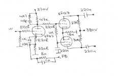
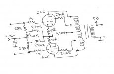
I have redrawn the schem into two separate sections to be more clearer .
Please see the values of components if they’re correct.
Any tips and hints is acceptable!!
I don’t know the amount of FB ,yet. That’s why I’m writing Rx and Cx. I’m designing the PSU write now .Hope to post it today , to have your opinion.
I see that arnoldc designs his circuits with MC7 (MicroCap 7) .I have downloaded MC evaluation 7 demo and the tubemods but I can’t run any mode ‘cause it says that I must convert it from MC4 version to MC7.How can this be done?
If you don’t know please contact arnoldc if he can help me. Does anyone have the original MC 7 program to send it by e-mail to me??? Please zipped!
Yup! 66.5V RMS at each output (OUTA, OUTB). 188V P-P, 133V RMS between the two, that's at 500mV input no feedback. That's if my math is correct!
My calculations aren’t the same. Please see again mine ‘cause I’d like to know if I’m thinking right.
With 0.5 Vrms input I’ll have 47,2 Vrms ( gain 39,5 db or 94.4 -as it is in arnoldc’s schem) at each output of the phase splitter . So 47,2*2=94,4 V rms from grid to grid .
The SV6L6 PP output stage needs peak 70 V grid to grid voltage or 49,49 V rms . So with an input about 0,25Vrms and without feedback I can drive the output stage at full power and have 30W .
I have redrawn the schem into two separate sections to be more clearer .
Please see the values of components if they’re correct.
Any tips and hints is acceptable!!
I don’t know the amount of FB ,yet. That’s why I’m writing Rx and Cx. I’m designing the PSU write now .Hope to post it today , to have your opinion.
Attachments
@resident
The bias circuit for the output stage doesn't look right, swap (juxtapose) the 68k and 270k resistors on each 6L6. The way it is the driver stage will see about 91k, should be closer to 270k-300k when you swap them around. And make sure the resistors are matched to within 2% or better.
The driver stage... Change the 220nF cap that goes from the grid of the cathode driven stage to 470nF, up to about 2uF max. Too high of value here will cause what's called blocking distortion. This cap will influence the sound of the driver stage more than any other componet, so use the best you can afford at this spot.
Also you have a 1k grid leak resistor at the input of the 1st stage (typo?), should be 100k to 270k, 470k max, depends on what you're planning on driving the amp with!
The diagram/sim was done by yours truely, using mc6. Sorry I can't help you there! Against THE RULES!!! IIRC aronoldc uses tubecad. Try downloading SwitcherCad, from Linear Technologies. Go here to learn more...
www.duncanamps.com
Wayne 🙂
The bias circuit for the output stage doesn't look right, swap (juxtapose) the 68k and 270k resistors on each 6L6. The way it is the driver stage will see about 91k, should be closer to 270k-300k when you swap them around. And make sure the resistors are matched to within 2% or better.
The driver stage... Change the 220nF cap that goes from the grid of the cathode driven stage to 470nF, up to about 2uF max. Too high of value here will cause what's called blocking distortion. This cap will influence the sound of the driver stage more than any other componet, so use the best you can afford at this spot.
Also you have a 1k grid leak resistor at the input of the 1st stage (typo?), should be 100k to 270k, 470k max, depends on what you're planning on driving the amp with!
The diagram/sim was done by yours truely, using mc6. Sorry I can't help you there! Against THE RULES!!!
IIRC aronoldc uses tubecad. Try downloading SwitcherCad, from Linear Technologies. Go here to learn more...www.duncanamps.com
Wayne 🙂
@ arnoldc
How much cost the tubeCAD and SE cad? 🙁
Oups...
Yes ,typo! 🙂
What about Audyn MKP?
I woke up this morning with an interesting idea.
What do you say to try an OPT with CFB configuration???Like the famous QUAD??
And bias the 6L6 with CFB??
How much cost the tubeCAD and SE cad? 🙁
Also you have a 1k grid leak resistor at the input of the 1st stage (typo?),
Oups...
Yes ,typo! 🙂
This cap will influence the sound of the driver stage more than any other componet, so use the best you can afford at this spot.
What about Audyn MKP?
I woke up this morning with an interesting idea.
What do you say to try an OPT with CFB configuration???Like the famous QUAD??
And bias the 6L6 with CFB??
resident said:@ arnoldc
How much cost the tubeCAD and SE cad? 🙁
$40 each. seaa www.glass-ware.com for description and www.tubesandmore.com for purchase info. i think they're on sale now.
@ arnoldc
Hmm.
Thank you!
They're not very expensive.🙂
What do you say about my idea to go with CFB configuration??
Hmm.
Thank you!
They're not very expensive.🙂
What do you say about my idea to go with CFB configuration??
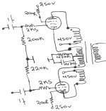
A first approach on 6L6 P-P CFB output stage. 🙂
I'm reading and reading and...any help?
As a newbie I'm not sure on what I'm doing. 🙁
I'll do some more searches on internet ,books,mags,e.t.c. and I'll post more details later.
I don't know if this schem is correct. 🙁
I'm reading and reading and...any help?
As a newbie I'm not sure on what I'm doing. 🙁
I'll do some more searches on internet ,books,mags,e.t.c. and I'll post more details later.
I don't know if this schem is correct. 🙁
Attachments
@resident
You pob don't want to hear this butt... as being a noobie I'd stick with a much easier to impliment (and cheaper too...) PP Ultralinear as a first project. Or maybe even a SE 6BQ5 or 6AQ5!
I've built a SE 6AQ5, many yrs ago! The 6AQ5 was originally used as the audio output in old B&W TV's back in the 50's & 60's.
With 250V @ the screen and plate, 45ma plate current, 4.5mA screen current @idle (no sig), 5.5k OPT primary you should get around 4.5 watts, 6 watts using a 6BQ5. And it sounds pretty darn good if using high quality parts and with a good PSU and layout. Tube rectification w/a 6CA5 with a good CLC filter following is a nice option here!
Just thought I'd throw out a few ideas at'cha! Tube Cad Journal has a nice app called Push-Pull Calculator, were you can do some sims of Triode or Triode connected pentodes and Beam tetrodes in Push Pull config. I use it all the time. It's a really nice tool and saves you a lot the MATH! Cheap too! Duncanamps (Duncan Munroe) has a lot of very good tools to download at His site and they're free too, (PSUDesigner comes to mind), so give'm a try!
There's also a lot of Dynaco variants out there on the web you could buld. I'll do my best to help you and I WILL post some schems ASP!
Good luck!
Wayne 😉
Originally posted by cogsncogs
Yup! 66.5V RMS at each output (OUTA, OUTB). 188V P-P, 133V RMS between the two, that's at 500mV input no feedback. That's if my math is correct!
ooops! My math was right but I somehow forgot that when you put in 500mV for the sine gen, the voltage say 500mV, that's 500mV above and below zero or in other words 500mV pk or 1V pk-pk or 707mV RMS!
So I corrected my mistake and here in this graph explains it:
Wayne 😀
Attachments
- Status
- Not open for further replies.
- Home
- Amplifiers
- Tubes / Valves
- 30W UL 6L6P-P amp