I need to put a full range sub woofer line out after the volume control on an amp. The amps driver stage has a simple CR high pass filter in front of it cutoff at 70hz.The sub will be passed a buffered full range signal because subs already have their own low pass filter built in. Its a long cable, maybe 30 feet. I'm assuming a cathode follower buffer should be tapped off between the volume and HPF to feed the long cable. So changing the volume both bands stay proportional. I may want a pot on the cable driver to act as my "bass" control too, not sure yet, so I don't have to walk behind the sub.
I know some will say take it off the OPT, I do that often, this time my design goal is to free up the OPT from having to deal with bass so much. What can I say, I like subwoofers, for all genres, since I don't have room for big speakers that go much below 60hz anyway.
My main question is what tube (cathode follower) would you use to drive a very long subwoofer cable? High frequency rolloff is not an issue as this signal is going to low pass filtered anyway at the sub. But hum pickup is the fault mode I definitely am trying to not have. Or maybe I should drive the sub cable with a line out transformer, maybe a Jensen?
Last edited:
If you are trying to avoid hum, put the line transformer at the receiving end. And load that receiving end, don’t just let it look like a high impedance. Do that and you can just drive a twisted pair. Even a 10k load is better than floating, lower Z is better still. Use a follower with a high gm - I’ve even given thought to using EL84 balanced outputs on a preamp (vs. paralleled 6/12SN7) to make it capable of driving *anything*. 6V6’s have even been used. Use a few ohms of series R to avoid capacitive loads, as with all followers. Purists can even use 75 ohm, double terminated - but even “75 ohm” cable deviates from 75 ohms, significantly, at audio frequency.
Define "Very long"? I'm driving a 25 foot RCA with a 6N14P and there are no issues. I have PCB's for it also along with versions for 6N1P, 12AU7, and 6N3P.
Approx. 30 feet terminating at this subwoofer:
Golden Ear ForceField 5:
I use this sub with the speaker inputs currently or with the sub output of a receiver, receivers already have LPF on the sub out. However I just noticed that the line in of the sub apparently doesn't have a LPF built into the sub, only the speaker ins have that. I guess they don't bother putting LPF's on the line in level of subs because receivers already have a managed bass sub out. So I may have to put a small LPF in front of the line driver in my design. And if I simply use a smaller coupling cap after the driver I can have the HPF be that, and eliminate a capacitor, thinking I needed to put a HPF prior to the driver tube, duh.
So its just finding a good tube for a CF line driver, maybe just a good old 6SN7.

If you are driving 70Hz and lower frequencies to a subwoofer.
The capacitive reactance (impedance) of a 30 Foot cable at 70Hz is very high.
An RG52 coax cable, is 30pF/foot. 30pF x 30 feet = 900pF
900pF at 70 Hz is 2.5 Meg Ohms impedance.
There is no problem driving 70Hz down a 30 foot cable to the subwoofer amplifier.
However:
900pF at 20kHz has only 8.8k of capacitive reactance (8.8k impedance).
So any circuit that has all of these: 70Hz and lower frequencies, midrange frequencies, and tweeter frequencies, and has to drive a 30 foot cable might have a problem because of the low impedance at mid and high frequencies changing the load line of that circuit.
Only a careful study of the circuitry of your receiver as it relates to the sub output can determine if there is a problem driving that low impedance at mid and high frequencies.
Last edited:
I have not tried it in real life yet but I have looked at this in simulations. The 6DJ8/ECC88 appears to be able to drive a full range signal in to thousands of pf with no trouble (of course you could use a power triode I suppose). A subwoofer isn't going to care about the high frequencies. Is there any reason not to put a first or second order low pass at say 100Hz at the subwoofer output?
I have not tried it in real life yet but I have looked at this in simulations. The 6DJ8/ECC88 appears to be able to drive a full range signal in to thousands of pf with no trouble (of course you could use a power triode I suppose). A subwoofer isn't going to care about the high frequencies. Is there any reason not to put a first or second order low pass at say 100Hz at the subwoofer output?
The line in of modern subs are full range, so that means I need a simple RC low pass filter. My goal with this project was to intentionally relieve the OPT of deep bass by reducing the size of the coupling capacitor to roll off the power stage at, lets say 60hz. Then the LPF feeding the sub would roll off highs at 80hz. That gives 20hz and more of common overlap because the filters will be gradual 6db simple 1st order CR / LR filters. Because I am intentionally giving my OPT a break by relieving it of lows, I cant use the speaker inputs of the sub.
I'm sketching out a schematic for the subwoofer driver and LPF board and where in the circuit I will tap off, probably after the driver just before the amps coupling cap. That way the volume control works for everything and the sub driver board has some gain in front of it to compensate the LPF and CF losses.
I'm thinking the LPF and sub driver board will have a cathode follower, then the RC LPF followed by another cathode follower. This way the filter is unaffected by input / output loads or volume controls, because it is sandwiched between two CF's. The second CF then feds the sub. The first CF takes its input from wherever one wants to tap off of.
TAP OFF AMP DRIVER OUT ----> INPUT-CF ----> LPF ----> BASS LEVEL POT ----> OUTPUT-CF ----> LONG CABLE ----> SUBWOOFER IN
This little board will also have a sub woofer level control to act as my "bass" control. Not sure yet if it's worth putting in a switch to select from maybe 3 different LPF frequencies 60hz, 80hz, 100hz, it would be easy maybe the board should have it. Initially I'll try a 10K resistor with a .2 uf shunt capacitor, that will be approx. 80 hz LPF. As mentioned I'll roll off the power stage by just reducing the coupling cap
It should be a handy board because I really need my subwoofer, my speakers are Klipsch bookshelf speakers very transparent, smooth, dispersed and sensitive enough for flea watters, for the range they have. The sub fills them out nicely on the bottom. I could see dropping this board into all my projects.
I will post my schematic here sometime in the future as I think I'm finally making some headway. I'll have to breadboard it to make sure the bass level pot right after the LPF doesnt affect the cutoff freq with level changes, I dont think it will?
Last edited:
I have not tried it in real life yet but I have looked at this in simulations. The 6DJ8/ECC88 appears to be able to drive a full range signal in to thousands of pf with no trouble (of course you could use a power triode I suppose). A subwoofer isn't going to care about the high frequencies. Is there any reason not to put a first or second order low pass at say 100Hz at the subwoofer output?
Yes, 6DJ8 was one of my first choices, it has good amount of transconductance for CF's.
Seems like a good idea to get a board also.Define "Very long"? I'm driving a 25 foot RCA with a 6N14P and there are no issues. I have PCB's for it also along with versions for 6N1P, 12AU7, and 6N3P.
Maybe I've had too much beer tonight, but why not just drive the 'speaker' input with your buffered output? I've seen plenty of such inputs that don't require speaker levels or impedances. Measure or find out what the impedance actually is (may be 5k to 25k!), and the level required actually is, and from that we can design a proper buffer -- if necessary. ")
Floating the input with a line-level transformer may still be necessary to stifle hum. But it's an expense in both $ and SQ -- if you don't really need it, leave it out. Why plan/buy something you may not need?
If it were me, I'd avoid simple first-order filters. With the rare exception of bass guitar performance rigs, the stop-band attenuation and phase performance is simply not adequate. Designing for a '20 Hz overlap' is a gross oversimplification.
Cheers
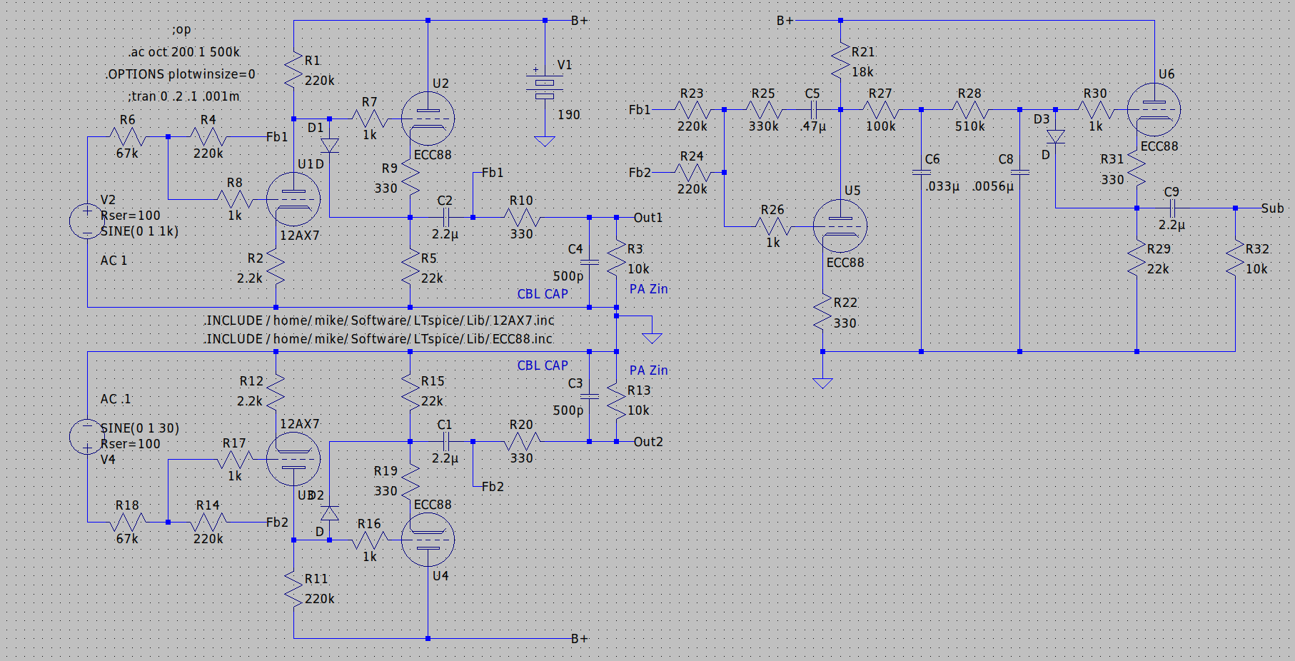
Sub outs are usually taken at the preamp. If you are doing it in the power amp I would take it before the VAS as the sub amp is going to be expecting no more than a couple of volts RMS. For what it is worth here is a preamp design I am working on with a sub out. Note that I have a simulated cable capacitance on the main outputs and I ran that up to 9000pf and still showed a high frequency roll off (-3db) starting above 30kHz.
Attachments
If it were me, I'd avoid simple first-order filters. With the rare exception of bass guitar performance rigs, the stop-band attenuation and phase performance is simply not adequate. Designing for a '20 Hz overlap' is a gross oversimplification.
Proper filtering is always needed somewhere in the chain. Either in the sub itself, from LFE, or a low pass inserted. Chances are you need about 4th order for it to sound like anything other than “booooooooooommmmm”. If it were me I’d use DSP unit to dial in the required filtering by ear or measurement, and then implement it however you see fit. If an LFE output was working to your satisfaction, implement that filter. It will be more than just an RC. 4 cascaded RC’s often works, but not always, and still requires experiment to get right. If you’re playing with k-followers anyway, you can make Sallen-Key filters and gyrators out of them to make whatever filter you need.
If your preamp and sub both have 3 prong power cords you WILL need a transformer to break the ground loop. There are rare instances when you can get away without it, but with 3 prong power cords it is the exception. Home brew tube amps/preamps usually have 3 prong power cords (or should). Consumer electronic preamps/receivers never have a 3 prong cord, which is why most HT systems can get away without a transformer going to the sub. The little “200 Hz capable” $6 Triads will work as an experiment. They go below 20 when driven from 600 ohm sources. If you get hum without and none with, then you can justify a more expensive transformer.
All my stuff gets mixed pro/home use, so transformer or balanced in is the rule. And why I suggested even beefier followers - l like getting output Z under 100 ohms. If 600 is fine, you can use mini novals, and there are a lot of choices. Don’t discount small signal pentodes for making high gm as a k follower (and TV tubes are cheap).
Sub outs are usually taken at the preamp. If you are doing it in the power amp I would take it before the VAS as the sub amp is going to be expecting no more than a couple of volts RMS. For what it is worth here is a preamp design I am working on with a sub out. Note that I have a simulated cable capacitance on the main outputs and I ran that up to 9000pf and still showed a high frequency roll off (-3db) starting above 30kHz.
Thanks! This is very close to what I was thinking but my power stage will be coupled by A simple CR HPF (switchable to low cut or full range by paralleling another coupling cap). So I would be taking my sub tap prior to the amps main coupling cap. Also can you simulate if R3 and R13 can be a pot bass level control without that load change screwing up the LPF cutoff frequency? I was going to add a CF after the LPF but deciding if the bass level pot should be right after the filter or right after the final CF at the out jack. Why no bass level control in your design? Is your subwoofer conveniently located?
Proper filtering is always needed somewhere in the chain. Either in the sub itself, from LFE, or a low pass inserted. Chances are you need about 4th order for it to sound like anything other than “booooooooooommmmm”. If it were me I’d use DSP unit to dial in the required filtering by ear or measurement, and then implement it however you see fit. If an LFE output was working to your satisfaction, implement that filter. It will be more than just an RC. 4 cascaded RC’s often works, but not always, and still requires experiment to get right. If you’re playing with k-followers anyway, you can make Sallen-Key filters and gyrators out of them to make whatever filter you need.
If your preamp and sub both have 3 prong power cords you WILL need a transformer to break the ground loop. There are rare instances when you can get away without it, but with 3 prong power cords it is the exception. Home brew tube amps/preamps usually have 3 prong power cords (or should). Consumer electronic preamps/receivers never have a 3 prong cord, which is why most HT systems can get away without a transformer going to the sub. The little “200 Hz capable” $6 Triads will work as an experiment. They go below 20 when driven from 600 ohm sources. If you get hum without and none with, then you can justify a more expensive transformer.
All my stuff gets mixed pro/home use, so transformer or balanced in is the rule. And why I suggested even beefier followers - l like getting output Z under 100 ohms. If 600 is fine, you can use mini novals, and there are a lot of choices. Don’t discount small signal pentodes for making high gm as a k follower (and TV tubes are cheap).
Oh boy lots to chew on here, and you resurrected some long forgotten memories. I definitely don't want the long slow boooom effect, been there in the 80's when I first started playing with bass management and the filters available then. And you're right about the ground loop, been there too. Even the 1st order LPF I have to re-think a lot here even to the point of using a mini dsp. Bass management isn't easy, thats why I have a 25 foot cable in the first place, the room simply wants my sub where it is! I may reduce my project scope to implementing a low-cut full-range HPF switch in the main amp, tap out a simple full range CF prior to the coupling cap(s) and just provide an output jack. Then I could use that jack for DSP or trying to go into the speaker ins on the sub (which has LPF), or other means. Thanks!
Thanks! This is very close to what I was thinking but my power stage will be coupled by A simple CR HPF (switchable to low cut or full range by paralleling another coupling cap). So I would be taking my sub tap prior to the amps main coupling cap. Also can you simulate if R3 and R13 can be a pot bass level control without that load change screwing up the LPF cutoff frequency? I was going to add a CF after the LPF but deciding if the bass level pot should be right after the filter or right after the final CF at the out jack. Why no bass level control in your design? Is your subwoofer conveniently located?
R3 and R13 are just simulating the input impedance of the amplifier that the preamp is driving. In reality I would have a largish resistor there to discharge the output cap when no load is connected. The parallel caps there are just to simulate the capacitance of a cable and is not an actual part at all. If you want to simulate an input level control on the amp change those resistors to a series string of two resistors with a tap between them feeding the input circuitry of the amp.
A White CF is the proper way to drive a transmission line. An ordinary CF drives the line capacitance in the +ve direction only. High Gm is required.
In the -ve direction the line capacitance depends on the cathode resister, not as effective. 5687 or 7119 would be OK for a White CF.
Driving the line at 70 Hz is trivial. Some coax are low capacitance at 20 pF/Foot.
The power amp sounds like SS. Why are you driving the line with toobs?
In the -ve direction the line capacitance depends on the cathode resister, not as effective. 5687 or 7119 would be OK for a White CF.
Driving the line at 70 Hz is trivial. Some coax are low capacitance at 20 pF/Foot.
The power amp sounds like SS. Why are you driving the line with toobs?
I need to put a full range sub woofer line out after the volume control on an amp. The amps driver stage has a simple CR high pass filter in front of it cutoff at 70hz.The sub will be passed a buffered full range signal because subs already have their own low pass filter built in. Its a long cable, maybe 30 feet. I'm assuming a cathode follower buffer should be tapped off between the volume and HPF to feed the long cable. So changing the volume both bands stay proportional. I may want a pot on the cable driver to act as my "bass" control too, not sure yet, so I don't have to walk behind the sub.
I know some will say take it off the OPT, I do that often, this time my design goal is to free up the OPT from having to deal with bass so much. What can I say, I like subwoofers, for all genres, since I don't have room for big speakers that go much below 60hz anyway.
My main question is what tube (cathode follower) would you use to drive a very long subwoofer cable? High frequency rolloff is not an issue as this signal is going to low pass filtered anyway at the sub. But hum pickup is the fault mode I definitely am trying to not have. Or maybe I should drive the sub cable with a line out transformer, maybe a Jensen?
It would be interesting to try out a good opamp configured as buffer. Like OPA1656. Can be made small too. Use a good +/- 12 ... 15V PSU with modern low noise regulators. Then compare to the tube buffer. From what I experienced topology does not matter much for bass use and performance with opamps has many plusses.
Low power, small, low output Z, absolutely no hum, almost no noise. Of course include a muting microrelay to avoid nasty power on/off plops.
Last edited:
- Home
- Amplifiers
- Tubes / Valves
- Driving a long cable, what tube to use?