Is CCS in CF overkill
In another thread on coupling AF to CF Hans (tubetvr) indicated that a CCS load on a CF biased with the grid at high voltage (as in direct coupled input) does not appreciably increase linearity (if I understood him correctly).
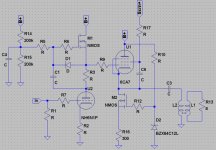
This makes me wonder if my circuit shown in post #37 is over kill. Maybe I should just use the CCS in the voltage amplification stages (i.e. the Mu-Stage circuit) and use a simple cathode resistor on the output stage (with the same para-feed transformer connection). On the other hand the added MOSFET CCS costs next to nothing and should improve the possible voltage swing no?
What is the consensus here?
SY what are your thoughts on this circuit?
In another thread on coupling AF to CF Hans (tubetvr) indicated that a CCS load on a CF biased with the grid at high voltage (as in direct coupled input) does not appreciably increase linearity (if I understood him correctly).
What I tried to say was that a CF with ~100V over the cathode resistor for reasonable output voltage is as linear as the same CF with a CCS, at least in practice, (when you look at the spectrum using a spectrum analyser). Only when you are trying to swing very high output voltage, (close to clipping) the CCS based CF is better. Spice simulations can show different results but it tells more about failings of tube spice models...
This about linearity of different CF circuits was described already in "Vacuum tube amplifiers" by Valley and Wallman where linearity curves are shown for CF with self bias, with neagtive voltage feeding high value resistors and with CCS, I though that was so interesting so I did my own measurements on different CF circuits, in my own preamp I use a CF with the cathode resistor connected to -100V so the output is at 0V.
Regards Hans
Re: Is CCS in CF overkill
Not so much the voltage swing, that is likely limited by your triode driver. However, it saps AC current, loading in parallel with the load resistance. RC coupled amplifiers are incredibly inefficient, and a CCS loaded one slightly more so.
If you really want power output, you should use an inductor or transformer in place of the CCS so you aren't burning half the damn supply voltage. You'll need a coupling capacitor and a very high voltage supply to the driver stage to swing the required drive, and a pentode under the mu stage wouldn't hurt.
Tim
mashaffer said:and use a simple cathode resistor on the output stage (with the same para-feed transformer connection). On the other hand the added MOSFET CCS costs next to nothing and should improve the possible voltage swing no?
Not so much the voltage swing, that is likely limited by your triode driver. However, it saps AC current, loading in parallel with the load resistance. RC coupled amplifiers are incredibly inefficient, and a CCS loaded one slightly more so.
If you really want power output, you should use an inductor or transformer in place of the CCS so you aren't burning half the damn supply voltage. You'll need a coupling capacitor and a very high voltage supply to the driver stage to swing the required drive, and a pentode under the mu stage wouldn't hurt.
Tim
So in this attached power amp circuit do you think that the CCS makes sense given the desire to swing as much voltage as possible?
I believe that Sch3mat1c already have given a good answer, my spontaneous thinking when I saw your circuit was that it would probably be better if you used the transformer directly connected in the cathode.
If you still want to use a transformer that has no DC current I would probably advice you to build a SRPP stage instead of using a CF with a SS based CCS, I believe that gives better result.
Regards Hans
I see your points. I was trying to avoid as much big iron as I could not just for cost but to avoid the eliptical load line but I suppose that as long as there is an output transformer the load "line" will not be linear anyway.
I guess that in principle I would not mind using a bigger PS but I suppose that as a practical matter it gets expensive.
I am thinking that a voltage swing of about 100 volts would be about right. I am thinking of a couple of possibilities. One is to use two triode based VAS stages and the other is to use an output stage that provides some voltage gain. My initial goal was to explore the possibilities of a CF output stage though so I want to exhaust all the possibilities of that approach before switching to another output topo.
I guess that the CCS approach is a bit easier in SS since the supply voltages are so much smaller. Throwing away 20 volts is less bothersome than throwing away 100 volts.")
Tim I assume that you are saying that RC is very inefficient, CCS is slightly more efficient but not nearly as efficient as an inductive load is that correct?
Am I right in the assumption that an inductive para-feed arrangement will have better frequency response and distortion than directly driving the output transformer?
I was also wondering if there was a simple way to protect the output transformer from an open circuit (possibly a zener, transistor or tube to switch a shunt resistor across the secondary when primary voltage exceeds a safe value; Or possibly to clamp the the output stage grid to ground.
I guess that in principle I would not mind using a bigger PS but I suppose that as a practical matter it gets expensive.
I am thinking that a voltage swing of about 100 volts would be about right. I am thinking of a couple of possibilities. One is to use two triode based VAS stages and the other is to use an output stage that provides some voltage gain. My initial goal was to explore the possibilities of a CF output stage though so I want to exhaust all the possibilities of that approach before switching to another output topo.
I guess that the CCS approach is a bit easier in SS since the supply voltages are so much smaller. Throwing away 20 volts is less bothersome than throwing away 100 volts.
Tim I assume that you are saying that RC is very inefficient, CCS is slightly more efficient but not nearly as efficient as an inductive load is that correct?
Am I right in the assumption that an inductive para-feed arrangement will have better frequency response and distortion than directly driving the output transformer?
I was also wondering if there was a simple way to protect the output transformer from an open circuit (possibly a zener, transistor or tube to switch a shunt resistor across the secondary when primary voltage exceeds a safe value; Or possibly to clamp the the output stage grid to ground.
mashaffer said:I see your points. I was trying to avoid as much big iron as I could not just for cost but to avoid the eliptical load line but I suppose that as long as there is an output transformer the load "line" will not be linear anyway.
Um... bigger iron means higher inductance and lower capacitance means straighter loadlines. And your speaker is about as non-ideal as a load can get!
I am thinking that a voltage swing of about 100 volts would be about right.I'm thinking a voltage swing of about (B+) peak to peak is right. That's what you need for the driver to fit its mouth around the CF, plus a bit more for gain lost in the output tube and low distortion at max. output. If B+ is 300V (what is it anyway?), I wouldn't mind seeing 400Vp-p capable. I doubt you have such luxury, so your output will be limited by the driver. Since voltage swing is limited, but current capability is nearly unaffected, you can decrease load resistance a tad to bring in more current and maximize output.
This is why I say a pentode would be a good driver, they can swing down to 20V above ground rather than a triode's 50 or 100V. In addition to that, gain is through the roof with CCS load; adding in a little shunt NFB ought to control it. Distortion will be better than triode, given the gain.
I am thinking of a couple of possibilities. One is to use two triode based VAS stages and the other is to use an output stage that provides some voltage gain. My initial goal was to explore the possibilities of a CF output stage though so I want to exhaust all the possibilities of that approach before switching to another output topo.
Ok. CF isn't any more dead now than when we started.
EDIT: Aww it edited it ^^^ dang you English, bug-ger-ing up words that aren't swears!
I guess that the CCS approach is a bit easier in SS since the supply voltages are so much smaller. Throwing away 20 volts is less bothersome than throwing away 100 volts.
And it's easy, for some reason, to blast away all the power and whatnot. Class A anything is horribly inefficient, and using resistors only makes it worse.
Tim I assume that you are saying that RC is very inefficient, CCS is slightly more efficient but not nearly as efficient as an inductive load is that correct?
Ya. A resistor dissipates both AC and DC (bias current/voltage) signals. A CCS provides an ice rink for the AC signals, but clearly sinks the same DC. An inductor stores *both* as a magnetic field, leaving only paratisic components such as DC resistance and hysteresis loss to get in the way.
Am I right in the assumption that an inductive para-feed arrangement will have better frequency response and distortion than directly driving the output transformer?
This is a bad question to ask. For instance, is it assumed that the OPT is suited to the task but otherwise equal (i.e. made to handle bias current vs. none; impedance, inductance, F response, etc. are the same)? If so, then a straight OPT will be better because you don't have the added inductance of the choke (being in parallel, it reduces system inductance), marginal LF loss due to the series cap and added weight of the two ferrous components. However, if the question makes the assumption that the OPT weight is the same (to say nothing of the choke load), the parafeed will win because it has more inductance than the air-gapped OPT which must handle DC bias current.
I was also wondering if there was a simple way to protect the output transformer from an open circuit (possibly a zener, transistor or tube to switch a shunt resistor across the secondary when primary voltage exceeds a safe value; Or possibly to clamp the the output stage grid to ground. [/B]
Aside from a fuse, nope. I suppose you could make an electric breaker which passes all current so long as the average (over a time constant of say .5 sec) doesn't exceed a value somewhat in excess of the bias current, but if it does, it switches off (open circuit) until its terminal voltage is reduced. Which is exactly what a resettable breaker does, except for the mechanical rather than electrical reset function.
Tim
I was trying to avoid as much big iron as I could not just for cost but to avoid the eliptical load line but I suppose that as long as there is an output transformer the load "line" will not be linear anyway.
On the contrary, if the output transformer is good enough, (if the primary inductance is high enough) the loadline with resistive load will be almost ideally straight even at very low frequencies as the primary inductance will not load the tube.
With a speaker you will get an elliptical loadline anyway regardless of transformer or not this is also true for a SS amplifier.
Regards Hans
- Status
- This old topic is closed. If you want to reopen this topic, contact a moderator using the "Report Post" button.
- Home
- Amplifiers
- Tubes / Valves
- Experiences with White CF/CCS CF output stage