Hi Everyone,
Someone has asked me to recap this vintage Ampex 600 tape machine preamp.
Before turning it on I was trying to trace out the internals and relate the insides to the schematic and noticed some weird extra stuff in one corner! The signal in off the mic seems to be hook directly to the high DC voltage rail! When I tested pin 2 of the XLR socket it read 319VDC!!!
Here is the vid I made which shows the additional components ...
Ampex preamp safety issue - YouTube
They don't seem to make any sense at all!
The original schematic is attached.
Does anyone have any idea why these extra components were added? What they were trying to do? It's strange because none of it looks like newly added stuff (the extra caps and resistors look as old as the rest of it).
Cheers
Tom, UK
Attachments
He said it he got a shock off a mic after a techy did some work on it. But that was relatively recently.
Seems a bit of an unsafe way to introduce phantom power but that might make sense. Can't seem to find anything online about ampex having a phantom power option for the 600 but I'll keep looking - cheers!
Seems a bit of an unsafe way to introduce phantom power but that might make sense. Can't seem to find anything online about ampex having a phantom power option for the 600 but I'll keep looking - cheers!
I've got a ACOP-4012XX7 microphone/preamp with a ½” polarised microphone capsule. A 5-pin Lemo socket connects that mic/preamp to a ACOP9200 interface that generates 200V for polarisation and 28V for preamp powering. So possibly the high DCV is for polarisation supply of a microphone.
Hi Everyone,
Someone has asked me to recap this vintage Ampex 600 tape machine preamp.
Before turning it on I was trying to trace out the internals and relate the insides to the schematic and noticed some weird extra stuff in one corner! The signal in off the mic seems to be hook directly to the high DC voltage rail! When I tested pin 2 of the XLR socket it read 319VDC!!!
Here is the vid I made which shows the additional components ...
Ampex preamp safety issue - YouTube
They don't seem to make any sense at all!
The original schematic is attached.
Does anyone have any idea why these extra components were added? What they were trying to do? It's strange because none of it looks like newly added stuff (the extra caps and resistors look as old as the rest of it).
Cheers
Tom, UK

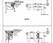
Tom, someone modified that Ampex 600 by connecting HT to the microphone connector through a 70k resistor. I suggest restoring the original mic input circuit as shown in the schematic and then test with audio. As shown in the schematic, the Ampex 600 was to be used with a high impedance microphone.
The easiest permanent "fix" for this machine to work with a standard 150 ohm microphone is to install and connect a mic input transformer. The primary of the transformer would go to pins 2 and 3 of the XLR connector (2 hot), and the secondary of the transformer would connect between the grid connection (hot) and ground (cold). The transformer case ground would go to the shield ground as shown in the schematic. There should be no HT on the mic input when a mic input transformer is used.
Sowter in the UK probably makes a small input transformer that will fit in the Ampex chassis near the input section (near the 5879 tube). You may find suitable transformers on ebay or through pro audio used/surplus equipment sources.
I own a Ampex 602-2 which still runs, and has the mic input transformers.
One more comment about phantom powering and mic input transformers: If done right, phantom powering can be used with input transformers as long as the phantom power voltage is brought up slowly. A sudden application of 48 volt phantom power to the primary of a mic input transformer will produce a high voltage spike across the secondary which can puncture transformer insulation, etc. and ruin a expensive component. In a Ampex machine, it may be possible to neatly wire in a resistive voltage divider and a regulator to supply a few milliamps of 48 v phantom power obtained from HT for microphones.
Thanks for your for the detailed reply rmb!
In fact just before I went to bed I found exactly what you are referring to in the 600 maintenance manual supplement pages - an input mod with a transformer.
I will certainly put it back to the original mic input as on the schematic and retest everything. Pretty sure it will be safe at least - especially now I have reattached an ground wire to the chassis.
I'll let you know what happens next!
Thanks again
Tom
Attachments
(the transformer mod imaga was attached to the previous post). I think that the customer just wants it safe and in orginal working condition with hum removed so he can resell so I prob won't be contacting Sowter to put in the input transforner - but thanks so much for the suggestion!
Thanks rmb - good to know of a decent supplier! I'll check out what the guy wants to do. If he wants an input transformer I'll def fit it for him (I just read my previous message and it reads as if I was thinking of asking sowter to install it - think I was tired when I wrote that one!). Cheers buddy.
Tom
Tom
- Home
- Amplifiers
- Tubes / Valves
- Dangerous Ampex Preamp!!!