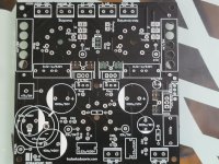
Enough talk. Here it is.
I call it the "Little Miracle" because of what it can do but still be 100mm square for economic purposes...
It uses one 6F12P and a pair of 6P43P/EL86/EL84/6BQ5/ whatever tube shares the pinout. Add power and OPT. 300V for B+ 600V for first stage (or 300V, with higher Dtot). I use isolation transformers with a Delon/quadrupler.
You can connect as triode, pentode, or UL by way of jumpers. Provisions are made for zener shunt screens.
You can use 2 400V 100uF or one 600V 47uF cap for the filters, that's why they overlap.. TL783/LM317 for CCS cathode biasing.
Rset is a test point, or omit the pot and install a fixed resistor.
PCB values are based on EL86/6P43P.
I'll sell a pair of these boards for 20$ shipped anywhere Canada Post will send mail. Kits available.
Attachments
Last edited:
Koda,
I missed this thread! On a topic very interesting to me. Could you post the schematic?
Thanks.
I missed this thread! On a topic very interesting to me. Could you post the schematic?
Thanks.
Sorry for the delay. I was in Montréal.
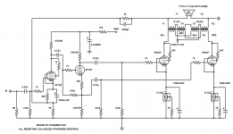
Et voilà.
Triode mode shown. UL and tetrode/pentode by jumper.
Also, the TL783 is only needed for 6P43P/EL86. If you build using 6BQ5/EL84/6P14P etc you can use LM317.
Et voilà.
Triode mode shown. UL and tetrode/pentode by jumper.
Also, the TL783 is only needed for 6P43P/EL86. If you build using 6BQ5/EL84/6P14P etc you can use LM317.
Attachments
Last edited:
The maximum cathode to heater voltage of the 6F12P (and the 6P43S) is 100 V. To what voltage does the filament supply has to be lifted? What is the cathode voltage of the triode section of the 6F12P at a B+ of 600 V?
This looks great! Must have been a lot of work to lay everything out so well and hook up all the tracks! Would be really good to see how you did the vias around the tube socket. It looks so neat.
I'm printing my first PCB at the moment and found that star grounding tends to encourage "organic" wiring.
How did you decide on the width of the traces to use?
I'm printing my first PCB at the moment and found that star grounding tends to encourage "organic" wiring.
How did you decide on the width of the traces to use?
The maximum cathode to heater voltage of the 6F12P (and the 6P43S) is 100 V. To what voltage does the filament supply has to be lifted? What is the cathode voltage of the triode section of the 6F12P at a B+ of 600 V?
I don't lift the heater. Although this exceeds the 100V stated maximum, these 6F12P tubes have run like this for literally years without any failures. The cathode voltage at 6F12P triode is 140VDC. The 12V connection is floating though, so it can be raised if desired. 75V or so would be fine. VR75 tube could be used instead of a resistive divider if you like orange glow.
This looks great! Must have been a lot of work to lay everything out so well and hook up all the tracks! Would be really good to see how you did the vias around the tube socket. It looks so neat.
I'm printing my first PCB at the moment and found that star grounding tends to encourage "organic" wiring.
How did you decide on the width of the traces to use?
Thank you. I think the layout took me about 2 hours and then a couple hours of tweaking the layout.. This board is revision V1.3. I added the holes under the hot parts and added the ability to use 2x100uF caps in series or one 47u/600V part (https://canada.newark.com/epcos/b43541b8476m000/cap-47-f-600v-alu-elec-snap-in/dp/16AC3106
I used a PCB width calculator like this: PCB Trace Width Calculator
And this calculator will give you an idea of how far the traces for HV and LV need to be separated.
PCB Trace Spacing Calculation for Voltage Levels
As far as 600V, I like high voltage 😀 but it's probably not necessary in most designs (just use 300V from the power stage) but I just effectively copied it from my MA-1 which uses the extra headroom for the gNFB loop. The 6P43P needs almost 30V of drive but the 6P45S needs more like 90V.
Koda
Last edited:
 Thread moved to Vendors
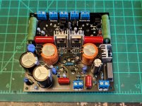
- Home
- Vendor's Bazaar
- The Little Miracle PCB