Clearly that wasn't the result of playing Mozart, right? 
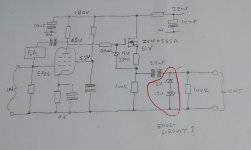
Whenever something grossly inappropriate happens at the input of a tube phono stage while powered, per example removing/inserting a phono cable you can expect many volts at output. Like maybe a hundred. As the current limiting resistor is only 330R this voltage can easily exceed the power dissipation of the zeners.
Rather unusual you had zeners there in the first place. Did something else downstream already blow up?
I see a problem that occurs when the circuit is first turned on . . .
The EF86 is cold
B+ is 0V
The 2.2uF has 0V across it.
Then . . . you turn the power on, the B+ comes on, and the plate of the cold EF86 is at full B+ voltage, so the Gate of the MOSFET is also at full B+ voltage.
The Source of the MOSFET pulls up very hard on its 330 Ohm Source resistor, and attempts to charge the 2.2uF capacitor, through the 12V Zener.
You have ((B+ Voltage) -12V) / 330 Ohms = a very large transient current attempting to charge the 2.2uF cap.
(a cap that starts at 0V charge, is a dead short, until it gets charged).
Does that describe what happened to your amplifier circuit?
I would agree with that but the HT has a filter resistor. Don't know what the value is but this would limit the dv/dt of the HT voltage raise - so its not as clear cut as that.
The resistor between the 220V and the 180V is 22K, the 180V also feed the left hand channel.
Solid state devices are not forgiving (like valves/tubes). So something like what 6A3sUMMER said is a plausible explanation. But I am not so sure... the B+ during turn-on spikes up to somewhere like 250V (or a bit higher even) on the EF86 plate. Ohm's law tells me that we will need 2mA to blow those 500mW Zeners.
What is the load on the EF86? if It is a big enough load then there is no way that 2mA is going to happen. So it has to be coming from somewhere else, right?
I would look to the mosfet follower. I would suspect a short from source to drain. This is a very common failure. A short from source to drain likely gets you the high voltage (with transient current during charging of the coupling cap) to make those zeners blow.
Personally, I use a reverse biased diode to protect exactly that same mosfet in addition to the zener to protect the gate (which I see you did). Some mosfets have this diode built in to the package, which is very nice. I do not believe this is the case for zvn0545a though.
Oh, and by the way, a constant current source will be far better than the 100k ohm resistor. Up to you though. Please post a complete schematic if you can find the time. you don't need to keep it a secret
Ian
Last edited:
baudouin0,
The 180V B+ that feeds both the EF86 plate resistor, and the MOSFET Drain is bypassed by a 10uV cap. The 22k resistor does not matter much, the charged 10uF cap driving a MOSFET and 330 Ohm resistor to a 12V zener does.
The time constant of the 22k and 10uF is only 0.22 seconds, the cap will charge much faster than the warmup time of an EF86 filament.
Essentially we have 10uF driving the MOSFET, driving 330 Ohms, driving a 12V Zener.
No transient relief.
But that is just how I see it.
Remove the 2.2uF coupling cap, and look at the junction of the 330 Ohm resistor and 100k resistor. It should be at 65V - the (slightly more than the Gate to Source threshold Voltage). If it passes signal, Either the MOSFET is doing that; Or the MOSFET is Open and the Gate to Source zener is passing the signal.
Once again, the real "Shorts" here are capacitors, they are 'dead' shorts at the start of a transient event.
A capacitor is a DC block, it is not an AC block.
Last edited:
I see a problem that occurs when the circuit is first turned on . . .
The EF86 is cold
B+ is 0V
The 2.2uF has 0V across it.
Then . . . you turn the power on, the B+ comes on, and the plate of the cold EF86 is at full B+ voltage, so the Gate of the MOSFET is also at full B+ voltage.
The Source of the MOSFET pulls up very hard on its 330 Ohm Source resistor, and attempts to charge the 2.2uF capacitor, through the 12V Zener.
You have ((B+ Voltage) -12V) / 330 Ohms = a very large transient current attempting to charge the 2.2uF cap.
(a cap that starts at 0V charge, is a dead short, until it gets charged).
Does that describe what happened to your amplifier circuit?
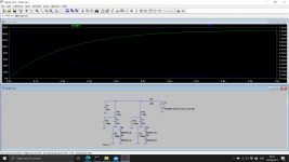
This is exactly what has happened, the B+ 10uF capacitor has an initial transient current of about 5mA I've measured it by lifting one end of the 22K resistor, very visible with the scope.
I'll also up the zener to 12V 3 watts.
I can't believe it not happen to anyone else that uses this mosfet arrange.
What would be the best to prevent it I have two options:
1. Delay timer circuit with a large value resistor and by-pass relay.
2. Soft start circuit using a LR8 regulator.
Thank to all for you help
This clamping circuit is not used in audio ... and the purpose is not very clear . I doubt something could blow up in normal use when switching sources , only in case the output capacitor will short , very unlikely .
A series resistor with the output could be a beter protection anyway .
A series resistor with the output could be a beter protection anyway .
Last edited:
At power up before valve starts to conduct its anode will be at B+ turning mosfet fully on and pushing loads of current through 330r and cap and zener's.
Incorrect; the 330R resistor and gate-source zener will limit any current a few milliamps, it's literally a current-limiting circuit. Nowhere near enough to pop the 0.5W output zeners, unless the OP has wired the circuit wrong...You have ((B+ Voltage) -12V) / 330 Ohms = a very large transient current attempting to charge the 2.2uF cap.
5mA is not enough to pop those zeners.This is exactly what has happened, the B+ 10uF capacitor has an initial transient current of about 5mA
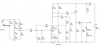
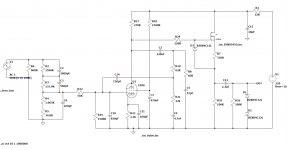
That's not the same as in your original post, where is the 330R and gate-source limiting Zener?This is the circuit for my EF86 it based on the Quad 22 phonostage.
Last edited:
In that case you've either made a wiring mistake or the surge came from outside, feeding into the output. The MOSFET cannot damage the clamping zeners.The circuit was base on the Quad 22 phonostage.
This is the circuit I've used.
- Home
- Amplifiers
- Tubes / Valves
- EF86 with mosfet follower clamping diodes short circuit?


