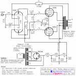
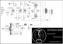
In an attempt to keep things simple with my first "scratch" build, I went with the attached Dynaco 410a circuit. Although I find the sound to be pretty decent to my ears, I feel like I'm not getting the levels I should since I'm not running a preamp but just direct in from a Node streamer with a volume control wired in ahead of the input stage. I'm not savvy enough at this point to calculate the gains of various stages precisely (still learning) but wanted your opinion on the second circuit (Evil Science). I can convert to this without major expense and it appears to be a more refined circuit which I assume would work with 8k output transformers.
Attachments
IMO, both designs have their shortcomings.
The Evil Science circuit employs the non-linear 12AU7/ECC82. However, that is easily corrected by substituting 12BH7s for the 12AU7s. The passive parts values do not change. Just make sure you have plenty of heater current available, as 12BH7s draw twice as much heater current as 12AU7s.
The Dyna 410A has, what I regard to be, significant problems. Paraphase phase splitter topology, which (for good reason) is currently out of favor, is employed. Also, the quite wimpy 6SL7 is being asked to drive the Miller capacitance of ultra-linear (UL) mode O/P tubes.
IMO, tweaking the Evil Science setup to eliminate 'U7 non-linearity is clearly the better choice. An interesting option for the I/P voltage amplifiers is the Loktal 7AF7. Loktal and Octal sockets occupy (roughly) the same "real estate" and the 7AF7 is nicely linear, while drawing only 300 mA. of heater current.
The Dyna 410A has, what I regard to be, significant problems. Paraphase phase splitter topology, which (for good reason) is currently out of favor, is employed. Also, the quite wimpy 6SL7 is being asked to drive the Miller capacitance of ultra-linear (UL) mode O/P tubes.
Yeah, this is what I've been reading up on so I'm at a bit of a loss on my gain issue as this should be supplying pretty good level to the power section, esp as I'm using a 12ax7 in place of the 6sl7. It seems to me that a lot of hifi builds have gone away from 12ax7s towards the 12au despite the issues you suggest. I would hate tho have a design with less gain.
I would hate tho have a design with less gain.
Cascaded medium μ triodes easily achieve the same net gain as what is effectively a single high μ triode, in the paraphase setup. While it is overly simplistic, think 'X7 μ = 100 and 'U7 μ of 20 times 'U7 μ of 20 = 400. The Evil Science setup employs cascaded common cathode μ 20 triodes feeding a "concertina" phase splitter, which exhibits a tiny voltage insertion loss.
BTW, there is very little difference in net gain between the μ 70 6SL7 triode and the μ 100 12AX7 triode. The reason lies in the plate resistance (RP) of the 2 types. 12AX7 RP is > than 6SL7 RP and an increase in RP leads to a reduction in net gain. Physics is giving with 1 hand and taking away with the other.
@bubbazanetti
It is possible to dispose of 12AU7 non-linearity in the Evil Science design at a cost of only an additional 300 mA. of heater current. How? Share bottles between the 2 channels. Use 7AF7 sections as in the 1st gain stage, 12BH7 or 6FQ7 sections in the 2nd gain stage, and 12AU7 sections in the "concertina" phase splitter. The 'U7 triode is acceptable in the phase splitter role, given the absence of voltage gain.
You get to reuse the sockets already on hand. Only a Loktal socket need be purchased for the 7AF7.
Of the old "classic school" designs, with loop feedback around several stages plus the output transformer, my favorite is the Dynaco ST-35. In a modern context you would do as Eli suggests, and use a single 12AX7 valve for both channels' first stage and a single 12AU7, 12BH7, 6FQ7/6CG7, 5687 or similar for both channels' second (splitter) stage. Sensitivity for all old school designs can be adjusted some by varying the amount of loop feedback.
You might also look into a more modern design like the Baby Huey, which makes output transformer choice less critical.
YOS,
Chris
ps: If you just want a little more gain from your existing setup, reduce the 100R cathode-to-cathode resistor, maybe to 47R or 68R. And the 100uF cap is too small. Make it 470uF at least.
Last edited:
Chris,
I'm partial to the topology Evil Science used. It is (IMO) a combination of a line stage with an unbypassed cathode bias resistor and a modest net gain voltage amplifier DC coupled to a split load phase splitter PP power amp. The power section employs "classic" GNFB topology.
Implementing that topology with maximized open loop linearity is likely to produce a highly satisfactory result. The builder will have to empirically set phase compensation to match the O/P "iron" used.
It certainly has a lot to recommend it. If the Baby Huey topology was re-balanced to optimize it to include a gain stage after a volume control it would be improved by the re-balance.
....I feel like I'm not getting the levels I should since I'm not running a preamp but just direct in from a Node streamer with a volume control wired in ahead of the input stage. I'm not savvy enough at this point to calculate the gains of various stages......
??? What levels do you feel should you be getting? More? Less? Since you are not yet able to figure it, and apparently NODE can not be bothered to give output level specs, nobody can say if it is right or wrong, if you need a preamp, or a cut of gain, or a software setting, or bigger speakers.
Thanks all, your explanations are very helpful for someone just starting out, aside from my multimeter, my only diagnostic tools currently are my ears. I'm hoping to remedy that as I work my way up the knowledge ladder.
- Home
- Amplifiers
- Tubes / Valves
- 6V6 pp design comparison