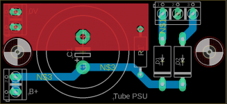
I made a PCB to hold 2 diodes, a cap and a bleeder resistor for use with a center-tapped transformer.
Upon initial test, fuses are blown.
Increasing the fuse size causes a momentary buzz from the transformer and then blown too.
If I disconnect the transformer leads from the PCB, the transformer is outputting 600 VCT so it seems to be fine.
It seems like there is an obvious mistake here that I'm overlooking.
The 600VCT wire leads are connected to pin 1 and 3 on the input, and the center-tap lead is connected to 0V output.
The parts I used were:
2x MUR460 diodes
150K 2W bleeder resistor
220uF 450V snap-in capacitor.
Thoughts?
Attachments
I can't see any mistakes.
What fuses do you use - fast or slow?
Feeding the SS rectifier directly to the 220uF cap makes for huge surge current.
Are the diodes OK?
What fuses do you use - fast or slow?
Feeding the SS rectifier directly to the 220uF cap makes for huge surge current.
Are the diodes OK?
Just to recap the actual AC output from the transformer across the winding's --not the center tap is ---
Disconnect CT from "0".
Measure voltage between 1 and 3.
If it's not 600V AC, you mixed up the secondary terminals.
Between CT and any "end" must be 300V AC.
Measure voltage between 1 and 3.
If it's not 600V AC, you mixed up the secondary terminals.
Between CT and any "end" must be 300V AC.
Well, your connections seem correct as does the board layout. You must have a shorted diode or filter capacitor. But why use that diode? An MUR460 is a very fast recovery 600V (reverse voltage) rated device. You certainly don't need the speed and I'd use a higher voltage diode like a UF1007 (1KV). The surge current rating seems sufficient, but the voltage surge may not be enough. (spec here)
Wow, thanks all for chiming in super fast.
Voltages were 600V from 1 and 3 and 300V between either 1 and the CT.
The board is so simple it must have been something trivial so I tested each part and indeed one of the diodes was shorted!!
These are brand new parts from Mouser, that never happened to me before.
I have a lot of UF1007 and swapped 2 in, and the board works fine.
I chose it from the list published by Mark Johnson in the article "Soft Recovery Diodes Lower Transformer Ringing by 10-20X".
Voltages were 600V from 1 and 3 and 300V between either 1 and the CT.
The board is so simple it must have been something trivial so I tested each part and indeed one of the diodes was shorted!!
These are brand new parts from Mouser, that never happened to me before.
I have a lot of UF1007 and swapped 2 in, and the board works fine.
But why use that diode? An MUR460 is a very fast recovery 600V (reverse voltage) rated device. You certainly don't need the speed and I'd use a higher voltage diode like a UF1007 (1KV).
I chose it from the list published by Mark Johnson in the article "Soft Recovery Diodes Lower Transformer Ringing by 10-20X".
600V CT yields 300VAC between ground, the diodes will see approx 450VDC surge, even higher on a unloaded transformer, which is awfully close to maximum of 600VDC for the MUR460
BY2000 is quite good, i don't consider switching noise in diodes important.
I see you use eagle, next time right click the polygon, and increase insulation distance to approx 1/10'' for these kinds of boards.
BY2000 is quite good, i don't consider switching noise in diodes important.
I see you use eagle, next time right click the polygon, and increase insulation distance to approx 1/10'' for these kinds of boards.
Thanks for the additional tips v4lve lover.
A few follow up questions:
1) The transformer is actually 575VCT and I was measuring 600VCT because it was unloaded.
450VDC surge is 75% of the max rating, is that really close? Asking to know how to derate and choose parts in the future.
2) BY2000 does not seem to be stocked anywhere, any other good options?
3) Thanks for the tip and will do in the future. In this specific, I don't think there is anything within 1/10" of that polygon, would it have mattered?
Thats what I was getting at I have the spec. of the MUR460 up on another browser and maximum RMS(Vrms ) for it is 420Volts .
Thanks for the additional tips v4lve lover.
A few follow up questions:
1) The transformer is actually 575VCT and I was measuring 600VCT because it was unloaded.
450VDC surge is 75% of the max rating, is that really close? Asking to know how to derate and choose parts in the future.
2) BY2000 does not seem to be stocked anywhere, any other good options?
3) Thanks for the tip and will do in the future. In this specific, I don't think there is anything within 1/10" of that polygon, would it have mattered?
1: I usually use 3 times the AC voltage in PIV rating, but others will use a different rule of thumb
2: I will look, But BY1800 is in stock at TME.
3. Its good practice to always build in some clearance, or it will come to bite you in the hind once you start putting an entire ground plane on a PCB. Cause normally it holds about .1mm clearance, which is too little for reliable operation.
See if you can bring it up on a Variac, or use the dim bulb tester setup to energize it. How big is the fuse? Is it in the primary side of the power xfmr? Do you have the center-tap on the secondary connected? Also 600V for MUR460 is a bit on the low side; use a 1000V diode; they're cheap.
The board is so simple it must have been something trivial so I tested each part and indeed one of the diodes was shorted!!.
A new diode will blow if current surge is too strong.
Or reverse breakdown voltage rating is insufficient.
Bear in mind diode reverse breakdown voltage needs to be at very least twice peak input voltage. I tend to go for 2.5 times peak input voltage.
Thanks for the info. As mentioned I'll use a UF-5408 for this board, those are 1000V.
This did raise a bit of a concern for a different project where I am also using 600V diodes,
C3D02060F.
Although those will be used with a 0-250V transformer and 4 diodes in a full-wave bridge configuration so I'm assuming this is less of a concern.
This did raise a bit of a concern for a different project where I am also using 600V diodes,
C3D02060F.
Although those will be used with a 0-250V transformer and 4 diodes in a full-wave bridge configuration so I'm assuming this is less of a concern.
If you have a 250VAC transformer the positive peak will be 353 volts.
So when cap is charged to +353 volts and AC phase is negative the full voltage across the diode will be 706 volts.
So when cap is charged to +353 volts and AC phase is negative the full voltage across the diode will be 706 volts.
The diode takes twice the peak voltage.
The capacitor is charged to the peak voltage that is a bit over 1.4 times the RMS voltage and then the voltage has to go through a negative half cycle that is another 1.4 times the RMS voltage.
The voltages sure do add up. I don't blame that diode for going short circuit.
The capacitor is charged to the peak voltage that is a bit over 1.4 times the RMS voltage and then the voltage has to go through a negative half cycle that is another 1.4 times the RMS voltage.
The voltages sure do add up. I don't blame that diode for going short circuit.
amatuer mistake on my part, clearly.
for some reason I thought each diode would only see half the voltage and not the full peak.
in between testing this "faulty" PCB, to rule out an issue with the transformer I plugged it into a different PCB that has Cree C3D02060F rectifiers (2 diodes in full-wave mode, also rated for 600V), and that one actually worked fine during the entire duration of testing the amp, about 30 min.
- Home
- Amplifiers
- Tubes / Valves
- Help troubleshoot tube PSU ... blowing fuse