I have a bunch of VT136 and 12AT7s that I'd like to measure and characterize a bit.
Was thinking of making test circuit with a resistor selector switch on the plate and cathode circuits. Ground the grid, and use a pot to set the screen voltage
Then run various resistor combinations, measure Vc, Vp, deduce Ia then fit the data to get the Ia transfer function.
Is this right or am I omitting things?
I have a bunch of VT136 and 12AT7s that I'd like to measure and characterize a bit.
Was thinking of making test circuit with a resistor selector switch on the plate and cathode circuits. Ground the grid, and use a pot to set the screen voltage
Then run various resistor combinations, measure Vc, Vp, deduce Ia then fit the data to get the Ia transfer function.
Is this right or am I omitting things?
You are on the right track.
Do choose voltages/currents from the tube data leaflet.
12AT7 has a working point :
Plate 250V 10mA current at -2v at the grid.
See https://frank.pocnet.net/sheets/030/e/ECC81.pdf
In the simple-is-better sense, you've got the right idea, and this method will work. In many regards, the B+ operating voltage isn't precisely important; 200, 250, 300, 350 all just fine for most valves. The Ra or anode resistor will drop the voltage actually 'seen' by the anode in proportion to the current passing thru it. E = IR, and all that.
Use of selectable cathode resistors of well known values is also good, along with a couple of digital throw-away meters (you know, the former Radio Shack specials at $9.95 at the check out desk). One between GND and cathode, both for its voltage value, and by induction, the current passing thru the valve.
I would add — for safety and survivability of the el-cheapo meter — a resistive voltage divider between the anode and ground. 10 to 1 is just fine. 1.8 MΩ from plate to 200 kΩ, to ground.
This 2 MΩ stack won't significantly mung up the measurements, yet only presents ¹⁄₁₀ the voltage to the 2nd meter. And it offers an effective series impedance (Thévenin) of what, 180 kΩ? Most meters have input impedance on the order of many MΩ. So, you're measurements will be off 5%.
Who cares.
Its a curve.
Or… since it is a fixed divider, you can carefully measure a known voltage, then thru the divider-into-your-cheap-meter, figure out the actual 'divider' ratio, and add a 50 kΩ pot to the small side to make it exactly 10 to 1. Easy-peasy.
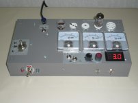
Now you've got a test instrument! Mount it in a small box, with clip-leads for your various sockets (hey… you're not building a full-on tube tester…).
Back when itsy-bitsy transistors were priced up there with golden chickens' teeth, I made a similar tester-in-a-box (with WW2 vintage amp meters!) for testing clipped-out-of-surplus-equipment transistors, to get a feel for their curves. When I was 13. Made me immensely happy to turn read-in-a-book theory into a practical circuit. Especially since in my tiny town, there were no gents that could even remotely be considered 'mentors'.
Good luck!
⋅-⋅-⋅ Just saying, ⋅-⋅-⋅
⋅-=≡ GoatGuy ✓ ≡=-⋅
PS... Here's something worth considering, too... the price certainly is right, and you could build 2 or 3 of them into the box. For less than $25 all-in including shipping.
XL830L LCD Multimeter Voltmeter Ammeter Circuit Tester Checker 0.36" LED Panel | eBay
Use of selectable cathode resistors of well known values is also good, along with a couple of digital throw-away meters (you know, the former Radio Shack specials at $9.95 at the check out desk). One between GND and cathode, both for its voltage value, and by induction, the current passing thru the valve.
I would add — for safety and survivability of the el-cheapo meter — a resistive voltage divider between the anode and ground. 10 to 1 is just fine. 1.8 MΩ from plate to 200 kΩ, to ground.
This 2 MΩ stack won't significantly mung up the measurements, yet only presents ¹⁄₁₀ the voltage to the 2nd meter. And it offers an effective series impedance (Thévenin) of what, 180 kΩ? Most meters have input impedance on the order of many MΩ. So, you're measurements will be off 5%.
Who cares.
Its a curve.
Or… since it is a fixed divider, you can carefully measure a known voltage, then thru the divider-into-your-cheap-meter, figure out the actual 'divider' ratio, and add a 50 kΩ pot to the small side to make it exactly 10 to 1. Easy-peasy.
Now you've got a test instrument! Mount it in a small box, with clip-leads for your various sockets (hey… you're not building a full-on tube tester…).
Back when itsy-bitsy transistors were priced up there with golden chickens' teeth, I made a similar tester-in-a-box (with WW2 vintage amp meters!) for testing clipped-out-of-surplus-equipment transistors, to get a feel for their curves. When I was 13. Made me immensely happy to turn read-in-a-book theory into a practical circuit. Especially since in my tiny town, there were no gents that could even remotely be considered 'mentors'.
Good luck!
⋅-⋅-⋅ Just saying, ⋅-⋅-⋅
⋅-=≡ GoatGuy ✓ ≡=-⋅
PS... Here's something worth considering, too... the price certainly is right, and you could build 2 or 3 of them into the box. For less than $25 all-in including shipping.
XL830L LCD Multimeter Voltmeter Ammeter Circuit Tester Checker 0.36" LED Panel | eBay
Last edited:
In the simple-is-better sense, you've got the right idea, and this method will work. In many regards, the B+ operating voltage isn't precisely important; 200, 250, 300, 350 all just fine for most valves. The Ra or anode resistor will drop the voltage actually 'seen' by the anode in proportion to the current passing thru it. E = IR, and all that.
Use of selectable cathode resistors of well known values is also good, along with a couple of digital throw-away meters (you know, the former Radio Shack specials at $9.95 at the check out desk). One between GND and cathode, both for its voltage value, and by induction, the current passing thru the valve.
I would add — for safety and survivability of the el-cheapo meter — a resistive voltage divider between the anode and ground. 10 to 1 is just fine. 1.8 MΩ from plate to 200 kΩ, to ground.
This 2 MΩ stack won't significantly mung up the measurements, yet only presents ¹⁄₁₀ the voltage to the 2nd meter. And it offers an effective series impedance (Thévenin) of what, 180 kΩ? Most meters have input impedance on the order of many MΩ. So, you're measurements will be off 5%.
Who cares.
Its a curve.
Or… since it is a fixed divider, you can carefully measure a known voltage, then thru the divider-into-your-cheap-meter, figure out the actual 'divider' ratio, and add a 50 kΩ pot to the small side to make it exactly 10 to 1. Easy-peasy.
Now you've got a test instrument! Mount it in a small box, with clip-leads for your various sockets (hey… you're not building a full-on tube tester…).
Back when itsy-bitsy transistors were priced up there with golden chickens' teeth, I made a similar tester-in-a-box (with WW2 vintage amp meters!) for testing clipped-out-of-surplus-equipment transistors, to get a feel for their curves. When I was 13. Made me immensely happy to turn read-in-a-book theory into a practical circuit. Especially since in my tiny town, there were no gents that could even remotely be considered 'mentors'.
Good luck!
⋅-⋅-⋅ Just saying, ⋅-⋅-⋅
⋅-=≡ GoatGuy ✓ ≡=-⋅
PS... Here's something worth considering, too... the price certainly is right, and you could build 2 or 3 of them into the box. For less than $25 all-in including shipping.
XL830L LCD Multimeter Voltmeter Ammeter Circuit Tester Checker 0.36" LED Panel | eBay
Thanks for that link. Ordered 3. Low expectations on quality but like you said all I need is the curve +/- generous. If it rejects an outlier it served its purpose.
you're welcome. I do hope you take and run with the idea of “putting it all in a small box” with a bundle of color-coded alligator clip-tipped leads coming out of the box.
Or posts, if you prefer (maybe posts for the B+, ground) …
and a place inside for the required 9 volt battery for the digital displays.
Although it is 'verboten' for this side to suggest such, sticking a smallish SMPS inside for the 300-to–400 volts would also seem to be a good idea.
It is your equipment and not something that a child's little inquisitive fingers is going to get ahold of.
alligators — 10 Pcs.- 5 Colors Test Lead & Alligator Clip Set AC-10 with 20.5" Length Wires | eBay
For a power supply, I would personally use a silicon diode based voltage-doubler, again in the box. For test instrument doodads, I see nothing wrong with direct line rectification. Everything on your bench is either grounded, or isolated. Right?
Indeed ... I think you could even stuff an itsy-bitsy 6 to 12 volt wall-wart type power supply in the same box for powering the digital 'meters'. Just plug in the whole box, and voila. It powers up. For safety, perhaps consider installing a DPDT relay inside too: Whether you remember to turn on, or off, the B+ high voltage, at least it'll cut out the B+ output until a momentary-contact switch is also pressed, to 'latch it on'. Unlatching is done by turning OFF the B+ switch.
I hope you will follow up someday with the 'picture show' of the thing.
And some curves!
GoatGuy
With me projects like these have the hazard of runaway feature creep. Next I would be noodling relay switched resistors all run and measured with an Arduino and spitting out the transfer function on the serial port.....
I already have a 250-0-250 transformer I can use for this and rotary switches are on the way from Amazon. I could probably get fancy and put it all in a Harbor Freight Pelican case knock-off. Hmm, let me see if I can CAD that up this weekend.
I already have a 250-0-250 transformer I can use for this and rotary switches are on the way from Amazon. I could probably get fancy and put it all in a Harbor Freight Pelican case knock-off. Hmm, let me see if I can CAD that up this weekend.
Yah, copy that. (creep)
The first thing I thought of was to Arduino-it … because it is easy, and there are shields that do all sorts of lovely analog-to-digital-and-back trickery. Cheap, too. But then the thing is FAR more instrumentation than you need to test out a small shoebox of valves. If however you intend to do a lot more, then … well … building a better mousetrap is pretty much An Engineer's Solution to the problem. And something to transload the results to one's … ahem … laptop, to make pretty curves in Excel.
See, this is my profession: 45 years (and growing) writing software, designing interfacing circuitry, mathematically working out how analog circuits are supposed to work, and that kind of thing. All in all, it is fun. All in all in all, project creep is real. An vexing when the intended super-duper-cool reasons for creeping the project don't materialize.
But that's what one gets after a 45 year long 'not-career' in this lovely technological era.
⋅-⋅-⋅ Just saying, ⋅-⋅-⋅
⋅-=≡ GoatGuy ✓ ≡=-⋅
I've done this (scroll down to the 'bridge rectifier' full-wave version):
linkie: DC Voltage Doubler and Voltage Multiplier Circuits working | ElecCircuit
Works surprisingly well, especially for instrumentation applications. Just about the easiest 340 volt DC supply off a 120 VAC input you can cobble together. Since you won't (likely) be delivering over 25 mA, then holding ripple down to a volt or so requires
⋅-=≡ GoatGuy ✓ ≡=-⋅
linkie: DC Voltage Doubler and Voltage Multiplier Circuits working | ElecCircuit
Works surprisingly well, especially for instrumentation applications. Just about the easiest 340 volt DC supply off a 120 VAC input you can cobble together. Since you won't (likely) be delivering over 25 mA, then holding ripple down to a volt or so requires
(di/dt / C)⋅Δt = ΔE
whereΔE = 1% of 350 volts = 3.5
Δt = ¹⁄₁₂₀ sec = 0.00833 sec
C = needed capacitor, in farads
di/dt = maximum current draw = 25 mA = 0.025 A
So…Δt = ¹⁄₁₂₀ sec = 0.00833 sec
C = needed capacitor, in farads
di/dt = maximum current draw = 25 mA = 0.025 A
C = 0.025 / (3.5 × 120)
C = 0.0000595 F
C = 56 µF or 68 µF at 400 VDC
Won't cost a bundle, and gets the job done. Unfortunately, I'm not the go-to guy for SMPS on-the-cheap sourcing. KodaBMX is… but I'ven't talked to him in awhile. Others might pipe up here, gods willing.C = 0.0000595 F
C = 56 µF or 68 µF at 400 VDC
⋅-=≡ GoatGuy ✓ ≡=-⋅
Thanks for that, since I already have a PT I think I will just go with that. If I want to rip it out and use for a better purpose (like my next PP amp) I can replace it with the doubler circuit.
Since I also want to test power pentodes what do you think about using VR tubes to supply a reference screen voltage? Or should I just stick with my original idea of using a 10K pot to dial it after I switch the cathode and plate resistors?
Since I also want to test power pentodes what do you think about using VR tubes to supply a reference screen voltage? Or should I just stick with my original idea of using a 10K pot to dial it after I switch the cathode and plate resistors?
I've done this (scroll down to the 'bridge rectifier' full-wave version):
linkie: DC Voltage Doubler and Voltage Multiplier Circuits working | ElecCircuit but I'ven't talked to him in awhile. Others might pipe up here, gods willing.
Works surprisingly well, especially for instrumentation applications. Just about the easiest 340 volt DC supply off a 120 VAC input you can cobble together. Since you won't (likely) be delivering over 25 mA, then holding ripple down to a volt or so requires(di/dt / C)⋅Δt = ΔEwhereΔE = 1% of 350 volts = 3.5⋅-=≡ GoatGuy ✓ ≡=-⋅
Δt = ¹⁄₁₂₀ sec = 0.00833 sec
C = needed capacitor, in farads
di/dt = maximum current draw = 25 mA = 0.025 A
Are those calculations to size the doubling capacitors in your link or is that for a filter capacitor that can put across the doubler output?
You're welcome.
Use the pot. Just make sure you order up a 5 watt part, so that it can dissipate all the (necessary) current passing thru it … to simulate a relatively low impedance voltage source.
That… and put a cap from center-tap to ground. Helps immensely.
I think you are good to go, .
Can't wait to hear feedback (ahem… err… ah… hmmm…) on this project.
⋅-=≡ GoatGuy ✓ ≡=-⋅
Are those calculations to size the doubling capacitors in your link or is that for a filter capacitor that can put across the doubler output?
Across the doubler output.
Short-changing the doubler's capacitors just limits the top voltage it can produce.
⋅-=≡ GoatGuy ✓ ≡=-⋅
As for 300V SMPS you can get close, but all the ones I have used were DC DC boost converters that ran from 12VDC. Just power that and the heaters from a 12V SMPS (or linear, I've done it).
If you're making a simple tester (I'm planning the same thing), I'd use a cheap "dial-a-volt" boost. It's noisy AF, but it's fine to test tubes with.
DC-DC 8-32V to 45~390V High Voltage Boost Converter ZVS Booster Mod F5X2 F0N8 | eBay
You could use one of these to get 6.3V from 12V for testing a single tube
1xDC-DC CC CV Buck Converter Step-down Power Module 7-40V to 1.2-35V 8A 300W | eBay
Just run the whole thing from a 12V 10A brick")
I hope all is well with you, sir GoatGuy!
If you're making a simple tester (I'm planning the same thing), I'd use a cheap "dial-a-volt" boost. It's noisy AF, but it's fine to test tubes with.
DC-DC 8-32V to 45~390V High Voltage Boost Converter ZVS Booster Mod F5X2 F0N8 | eBay
You could use one of these to get 6.3V from 12V for testing a single tube
1xDC-DC CC CV Buck Converter Step-down Power Module 7-40V to 1.2-35V 8A 300W | eBay
Just run the whole thing from a 12V 10A brick
I hope all is well with you, sir GoatGuy!
As for 300V SMPS you can get close, but all the ones I have used were DC DC boost converters that ran from 12VDC. Just power that and the heaters from a 12V SMPS (or linear, I've done it).
If you're making a simple tester (I'm planning the same thing), I'd use a cheap "dial-a-volt" boost. It's noisy AF, but it's fine to test tubes with.
DC-DC 8-32V to 45~390V High Voltage Boost Converter ZVS Booster Mod F5X2 F0N8 | eBay
I also want to test power tubes, can I get ~75ma (worst case) at HV with those boosters?
For short periods of time, yes. Longer if you cool it.
I would only test signal tubes with it myself.
This will power an entire EL84 PP stereo amp though. You can use a Delon doubler on the AC output for higher voltages.
DC-AC Converter 12V to 110V 200V 220V 280V 150W Inverter Boost Board Transformer | eBay
I would only test signal tubes with it myself.
This will power an entire EL84 PP stereo amp though. You can use a Delon doubler on the AC output for higher voltages.
DC-AC Converter 12V to 110V 200V 220V 280V 150W Inverter Boost Board Transformer | eBay
For short periods of time, yes. Longer if you cool it.
I would only test signal tubes with it myself.
This will power an entire EL84 PP stereo amp though. You can use a Delon doubler on the AC output for higher voltages.
Thanks for the suggestions. How about this one with a doubler?
https://www.amazon.com/Inverter-Con...boost+board+transformer&qid=1611334242&sr=8-4
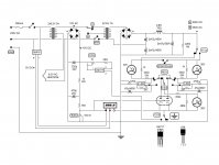
It's essentially the same thing with a different layout. Both use an SG3525 as the PWM controller driving a pair of MOSFETs into a coil. It only puts out AC though, and has no heatsinking.
I would add small heatsinks at least, and use diodes such as HER208 for the rectifiers. 1N4007 isn't fast enough for 20kHz and will fail as a short. Ask me how I know
Nice thing about SG3525 - the cap on pin 8 is a soft start cap (the electro in the corner). 22uF is the highest value allowed and will ramp the power over about 1 second instead of dropping the load all at once. This is handy if you use capacitors on the HV but your 12V supply can't start into the load.
- Status
- This old topic is closed. If you want to reopen this topic, contact a moderator using the "Report Post" button.
- Home
- Amplifiers
- Tubes / Valves
- Simple circuit for tube char and matching